INTERIOR PANELS / TRIM ROOF HEADLINING REASSEMBLY
CAUTION / NOTICE / HINT
- HINT:
- ·
Use the same procedure for RHD and LHD vehicles.
·The procedure listed below is for LHD vehicles.
PROCEDURE

 64714J
1.INSTALL DECK SIDE TRIM COVER RH
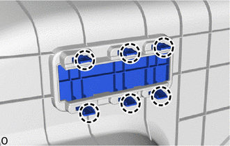
Attach the claw to install the deck side trim cover RH.
86101D
2.INSTALL NO. 3 ANTENNA CORD SUB-ASSEMBLY
82171
3.INSTALL NO. 1 ROOF WIRE (for LHD)
for Normal Roof:
Apply double-sided butyl tape as shown in the illustration.
- HINT:
-
Place the tape securely so that it is not misaligned or peeling.
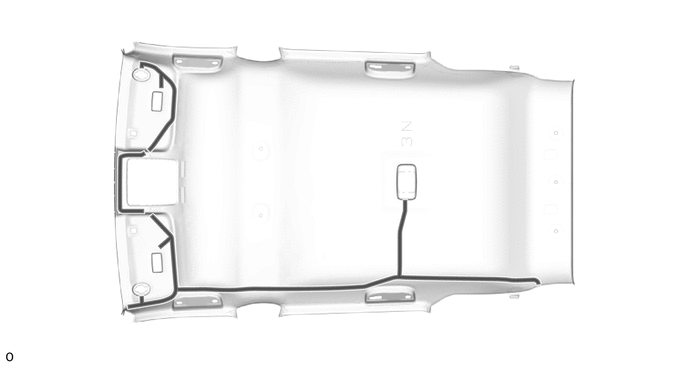

|
Double-sided Butyl Tape | - | - |
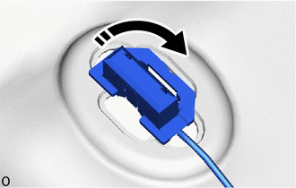

|
Install in this Direction |
Turn the visor connectors approximately 90° clockwise to install them to the roof headlining.
Attach the No. 1 roof wire to the double-sided butyl tape as shown in the illustration and secure the No. 1 roof wire with pieces of fastening tape.
- HINT:
- ·
Align the positioning tape of the No. 1 roof wire with the protrusion of the roof headlining and wrap fastening tape around them as shown in the part of the illustration labeled (A).
·Secure the No. 1 roof wire so that the positioning tape does not protrude from the cutout of the roof headlining as shown in the part of the illustration labeled (B).
·Adjust the extra length of the No. 1 roof wire in the part of the illustration labeled (C) and apply fastening tape.
·Align the positioning tape of the No. 1 roof wire with the marking on the roof headlining and apply tape as shown in the part of the illustration labeled (D).
·Apply the No. 1 roof wire so that it is securely attached and not twisted.
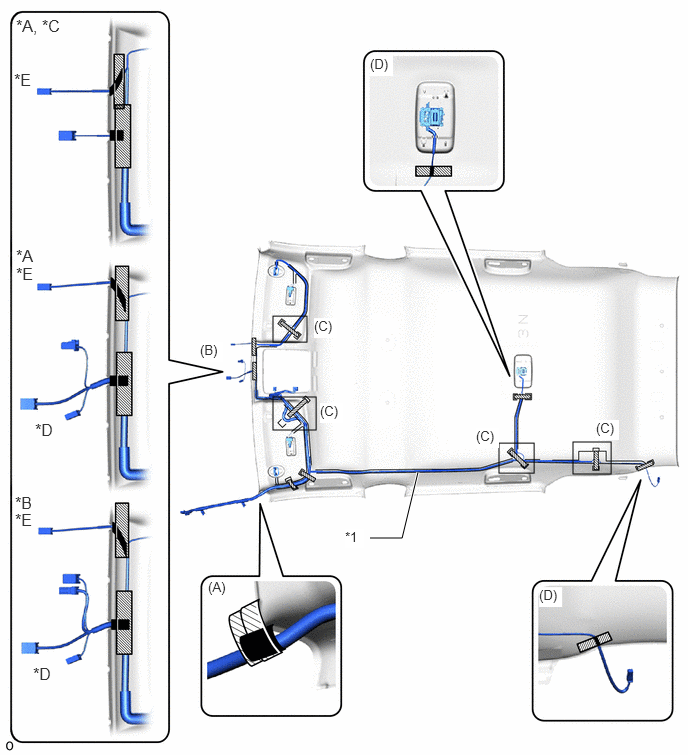
| *A | w/ EC Mirror | *B | w/ Digital Inner Mirror |
| *C | w/o Pre-collision System | *D | w/ Pre-collision System |
| *E | w/ Rain Sensor or w/ Humidity Sensor | - | - |
| *1 | No. 1 Roof Wire | - | - |

|
Fastening Tape | 
|
Positioning Tape |
for Moon Roof:
Apply double-sided butyl tape as shown in the illustration.
- HINT:
-
Place the tape securely so that it is not misaligned or peeling.
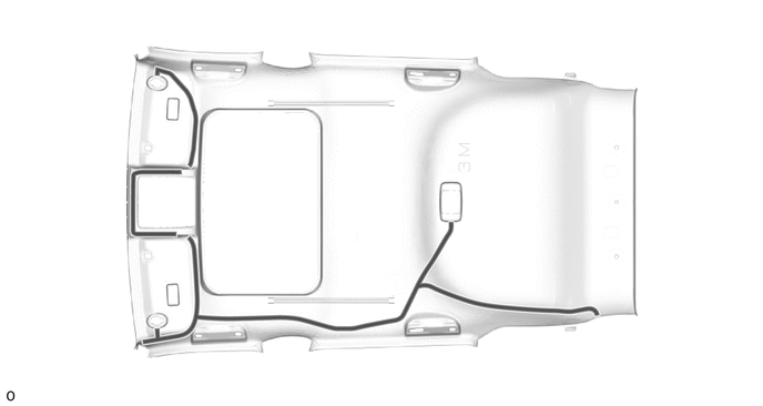
|
|
Double-sided Butyl Tape | - | - |
|
|
Install in this Direction |
Turn the visor connectors approximately 90° clockwise to install them to the roof headlining.
Attach the No. 1 roof wire to the double-sided butyl tape as shown in the illustration and secure the No. 1 roof wire with pieces of fastening tape.
- HINT:
- ·
Align the positioning tape of the No. 1 roof wire with the protrusion of the roof headlining and wrap fastening tape around them as shown in the part of the illustration labeled (A).
·Secure the No. 1 roof wire so that the positioning tape does not protrude from the cutout of the roof headlining as shown in the part of the illustration labeled (B).
·Adjust the extra length of the No. 1 roof wire in the part of the illustration labeled (C) and apply fastening tape.
·Align the positioning tape of the No. 1 roof wire with the marking on the roof headlining and apply tape as shown in the part of the illustration labeled (D).
·Apply the No. 1 roof wire so that it is securely attached and not twisted.
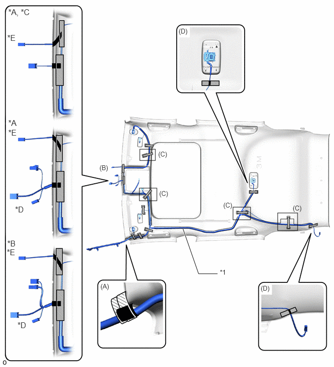
| *A | w/ EC Mirror | *B | w/ Digital Inner Mirror |
| *C | w/o Pre-collision System | *D | w/ Pre-collision System |
| *E | w/ Rain Sensor or w/ Humidity Sensor | - | - |
| *1 | No. 1 Roof Wire | - | - |
|
|
Fastening Tape |
|
Positioning Tape |
for Panoramic Moon Roof:
Apply double-sided butyl tape as shown in the illustration.
- HINT:
-
Place the tape securely so that it is not misaligned or peeling.
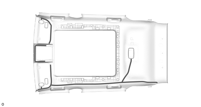
|
|
Double-sided Butyl Tape | - | - |
|
|
Install in this Direction |
Turn the visor connectors approximately 90° clockwise to install them to the roof headlining.
Attach the No. 1 roof wire to the double-sided butyl tape as shown in the illustration and secure the No. 1 roof wire with pieces of fastening tape.
- HINT:
- ·
Align the positioning tape of the No. 1 roof wire with the protrusion of the roof headlining and wrap fastening tape around them as shown in the part of the illustration labeled (A).
·Secure the No. 1 roof wire so that the positioning tape does not protrude from the cutout of the roof headlining as shown in the part of the illustration labeled (B).
·Adjust the extra length of the No. 1 roof wire in the part of the illustration labeled (C) and apply fastening tape.
·Align the positioning tape of the No. 1 roof wire with the marking on the roof headlining and apply tape as shown in the part of the illustration labeled (D).
·Apply the No. 1 roof wire so that it is securely attached and not twisted.
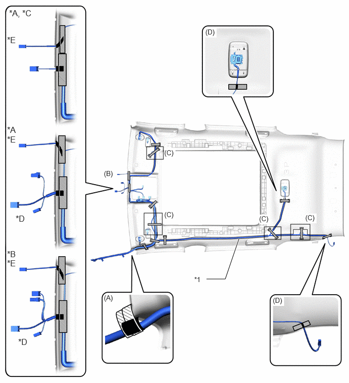
| *A | w/ EC Mirror | *B | w/ Digital Inner Mirror |
| *C | w/o Pre-collision System | *D | w/ Pre-collision System |
| *E | w/ Rain Sensor or w/ Humidity Sensor | - | - |
| *1 | No. 1 Roof Wire | - | - |
|
|
Fastening Tape |
|
Positioning Tape |
82171
4.INSTALL NO. 1 ROOF WIRE (for RHD)
for Normal Roof:
Apply double-sided butyl tape as shown in the illustration.
- HINT:
-
Place the tape securely so that it is not misaligned or peeling.
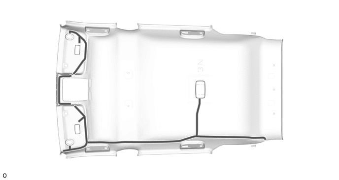
|
|
Double-sided Butyl Tape | - | - |
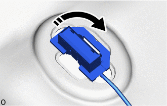
|
|
Install in this Direction |
Turn the visor connectors approximately 90° clockwise to install them to the roof headlining.
Attach the No. 1 roof wire to the double-sided butyl tape as shown in the illustration and secure the No. 1 roof wire with pieces of fastening tape.
- HINT:
- ·
Align the positioning tape of the No. 1 roof wire with the protrusion of the roof headlining and wrap fastening tape around them as shown in the part of the illustration labeled (A).
·Secure the No. 1 roof wire so that the positioning tape does not protrude from the cutout of the roof headlining as shown in the part of the illustration labeled (B).
·Adjust the extra length of the No. 1 roof wire in the part of the illustration labeled (C) and apply fastening tape.
·Align the positioning tape of the No. 1 roof wire with the marking on the roof headlining and apply tape as shown in the part of the illustration labeled (D).
·Apply the No. 1 roof wire so that it is securely attached and not twisted.
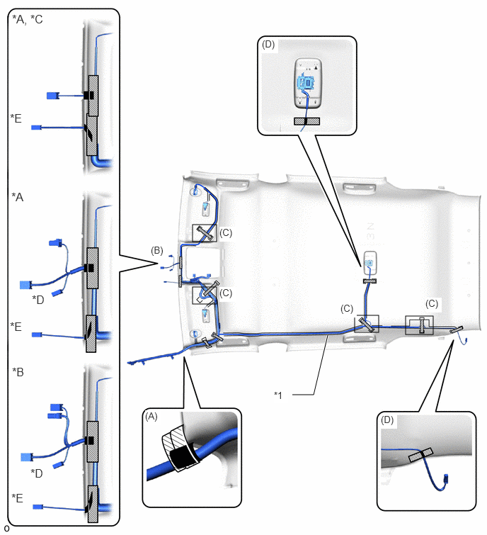
| *A | w/ EC Mirror | *B | w/ Digital Inner Mirror |
| *C | w/o Pre-collision System | *D | w/ Pre-collision System |
| *E | w/ Rain Sensor or w/ Humidity Sensor | - | - |
| *1 | No. 1 Roof Wire | - | - |
|
|
Fastening Tape |
|
Positioning Tape |
for Moon Roof:
Apply double-sided butyl tape as shown in the illustration.
- HINT:
-
Place the tape securely so that it is not misaligned or peeling.
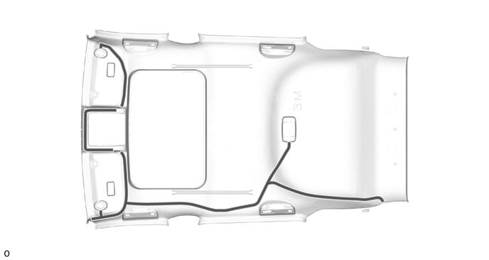
|
|
Double-sided Butyl Tape | - | - |
|
|
Install in this Direction |
Turn the visor connectors approximately 90° clockwise to install them to the roof headlining.
Attach the No. 1 roof wire to the double-sided butyl tape as shown in the illustration and secure the No. 1 roof wire with pieces of fastening tape.
- HINT:
- ·
Align the positioning tape of the No. 1 roof wire with the protrusion of the roof headlining and wrap fastening tape around them as shown in the part of the illustration labeled (A).
·Secure the No. 1 roof wire so that the positioning tape does not protrude from the cutout of the roof headlining as shown in the part of the illustration labeled (B).
·Adjust the extra length of the No. 1 roof wire in the part of the illustration labeled (C) and apply fastening tape.
·Align the positioning tape of the No. 1 roof wire with the marking on the roof headlining and apply tape as shown in the part of the illustration labeled (D).
·Apply the No. 1 roof wire so that it is securely attached and not twisted.
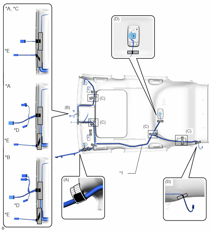
| *A | w/ EC Mirror | *B | w/ Digital Inner Mirror |
| *C | w/o Pre-collision System | *D | w/ Pre-collision System |
| *E | w/ Rain Sensor or w/ Humidity Sensor | - | - |
| *1 | No. 1 Roof Wire | - | - |
|
|
Fastening Tape |
|
Positioning Tape |
for Panoramic Moon Roof:
Apply double-sided butyl tape as shown in the illustration.
- HINT:
-
Place the tape securely so that it is not misaligned or peeling.
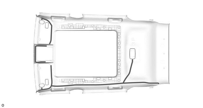
|
|
Double-sided Butyl Tape | - | - |
|
|
Install in this Direction |
Turn the visor connectors approximately 90° clockwise to install them to the roof headlining.
Attach the No. 1 roof wire to the double-sided butyl tape as shown in the illustration and secure the No. 1 roof wire with pieces of fastening tape.
- HINT:
- ·
Align the positioning tape of the No. 1 roof wire with the protrusion of the roof headlining and wrap fastening tape around them as shown in the part of the illustration labeled (A).
·Secure the No. 1 roof wire so that the positioning tape does not protrude from the cutout of the roof headlining as shown in the part of the illustration labeled (B).
·Adjust the extra length of the No. 1 roof wire in the part of the illustration labeled (C) and apply fastening tape.
·Align the positioning tape of the No. 1 roof wire with the marking on the roof headlining and apply tape as shown in the part of the illustration labeled (D).
·Apply the No. 1 roof wire so that it is securely attached and not twisted.
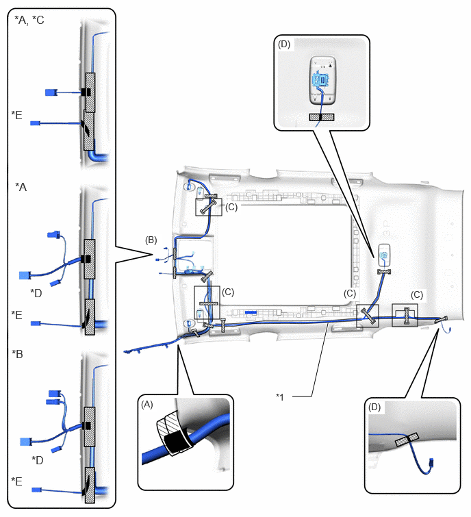
| *A | w/ EC Mirror | *B | w/ Digital Inner Mirror |
| *C | w/o Pre-collision System | *D | w/ Pre-collision System |
| *E | w/ Rain Sensor or w/ Humidity Sensor | - | - |
| *1 | No. 1 Roof Wire | - | - |
|
|
Fastening Tape |
|
Positioning Tape |
63342
5.INSTALL NO. 2 ROOF SILENCER PAD (for Panoramic Moon Roof, for Korea)
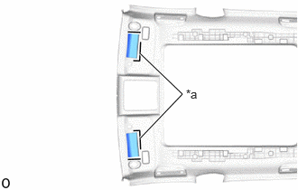
| *a | Marking |
Using double-sided butyl tape, install 2 new No. 2 roof silencer pads in the position shown in the illustration.
63354C
6.INSTALL ROOF HEADLINING FRONT SIDE PAD (for Panoramic Moon Roof, for Cold Area)
Remove the release paper from 2 new roof headlining front side pads.
- HINT:
-
After removing the release paper, keep the exposed adhesive free from foreign matter.
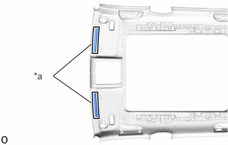
| *a | Marking |
Align the 2 roof headlining front side pads with the markings on the roof headlining assembly and install them as shown in the illustration.
63352C
7.INSTALL ROOF HEADLINING PAD END (for Panoramic Moon Roof)
Remove the release paper from 2 new roof headlining pad ends.
- HINT:
-
After removing the release paper, keep the exposed adhesive free from foreign matter.
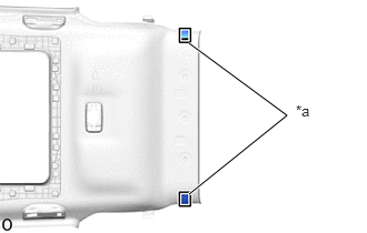
| *a | Marking |
Align the 2 roof headlining pad ends with the markings on the roof headlining assembly and install them as shown in the illustration.
63354C
8.INSTALL ROOF HEADLINING FRONT SIDE PAD (for Moon Roof, for Cold Area)
Remove the release paper from 2 new roof headlining front side pads.
- HINT:
-
After removing the release paper, keep the exposed adhesive free from foreign matter.
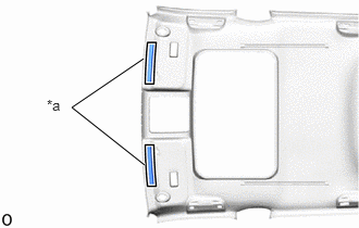
| *a | Marking |
Align the 2 roof headlining front side pads with the markings on the roof headlining assembly and install them as shown in the illustration.
63363
9.INSTALL NO. 3 ROOF HEADLINING SUPPORT (for Moon Roof, for Korea)
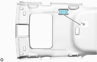
| *a | Marking |
Align the markings on the roof headlining assembly with the No. 3 roof headlining support and install them using hot-melt glue as shown in the illustration.
63364
10.INSTALL NO. 4 ROOF HEADLINING SUPPORT (for Moon Roof, for Korea)
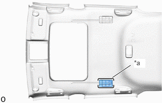
| *a | Marking |
Align the markings on the roof headlining assembly with the No. 4 roof headlining support and install them using hot-melt glue as shown in the illustration.
63361
11.INSTALL NO. 1 ROOF HEADLINING SUPPORT (for Moon Roof, for Korea)
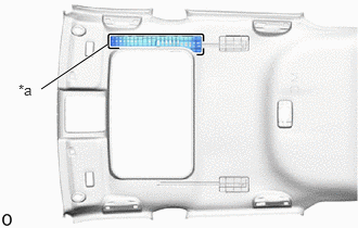
| *a | Marking |
Align the markings on the roof headlining assembly with the No. 1 roof headlining support and install them using hot-melt glue as shown in the illustration.
63362
12.INSTALL NO. 2 ROOF HEADLINING SUPPORT (for Moon Roof, for Korea)
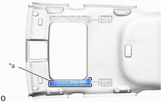
| *a | Marking |
Align the markings on the roof headlining assembly with the No. 2 roof headlining support and install them using hot-melt glue as shown in the illustration.
63342
13.INSTALL NO. 2 ROOF SILENCER PAD (for Moon Roof, for Korea)
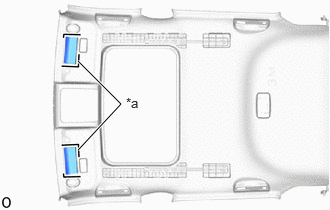
| *a | Marking |
Using double-sided butyl tape, install 2 new No. 2 roof silencer pads in the position shown in the illustration.
63355C
14.INSTALL ROOF HEADLINING PAD RH (for Moon Roof, for Korea)
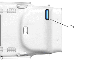
| *a | Marking |
Align the markings on the roof headlining assembly with the roof headlining pad RH and install them using hot-melt glue as shown in the illustration.
63356B
15.INSTALL ROOF HEADLINING PAD LH (for Moon Roof, for Korea)
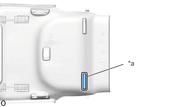
| *a | Marking |
Align the markings on the roof headlining assembly with the roof headlining pad LH and install them using hot-melt glue as shown in the illustration.
63352C
16.INSTALL ROOF HEADLINING PAD END (for Moon Roof)
Remove the release paper from 2 new roof headlining pad ends.
- HINT:
-
After removing the release paper, keep the exposed adhesive free from foreign matter.
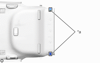
| *a | Marking |
Align the 2 roof headlining pad ends with the markings on the roof headlining assembly and install them as shown in the illustration.
63341
17.INSTALL NO. 1 ROOF SILENCER PAD (for Moon Roof)
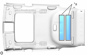
| *a | Marking |
Align 2 new No. 1 roof silencer pads with the silencer marking on the roof headlining assembly and install the 2 No. 1 roof silencer pads using hot-melt glue as shown in the illustration.
63355C
18.INSTALL ROOF HEADLINING PAD RH (for Normal Roof, for Korea)
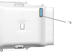
| *a | Marking |
Align the markings on the roof headlining assembly with the roof headlining pad RH and install them using hot-melt glue as shown in the illustration.
63356B
19.INSTALL ROOF HEADLINING PAD LH (for Normal Roof, for Korea)
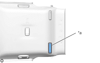
| *a | Marking |
Align the markings on the roof headlining assembly with the roof headlining pad LH and install them using hot-melt glue as shown in the illustration.
63342
20.INSTALL NO. 2 ROOF SILENCER PAD (for Normal Roof, for Korea)
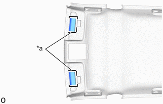
| *a | Marking |
Using double-sided butyl tape, install 2 new No. 2 roof silencer pads in the position shown in the illustration.
63352D
21.INSTALL NO. 2 ROOF HEADLINING PAD (for Normal Roof, for Cold Area)
Remove the release paper from new No. 2 roof headlining pad.
- HINT:
-
After removing the release paper, keep the exposed adhesive free from foreign matter.
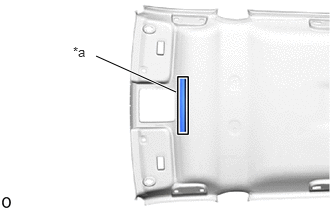
| *a | Marking |
Align the No. 2 roof headlining pad with the markings on the roof headlining assembly and install them as shown in the illustration.
63351B
22.INSTALL ROOF HEADLINING PAD (for Normal Roof, for Cold Area)
Remove the release paper from 2 new roof headlining pads.
- HINT:
-
After removing the release paper, keep the exposed adhesive free from foreign matter.
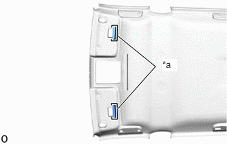
| *a | Marking |
Align the 2 roof headlining pads with the markings on the roof headlining assembly and install them as shown in the illustration.
63354C
23.INSTALL ROOF HEADLINING FRONT SIDE PAD (for Normal Roof, for Cold Area)
Remove the release paper from 2 new roof headlining front side pads.
- HINT:
-
After removing the release paper, keep the exposed adhesive free from foreign matter.
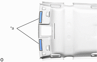
| *a | Marking |
Align the 2 roof headlining front side pads with the markings on the roof headlining assembly and install them as shown in the illustration.
63361
24.INSTALL NO. 1 ROOF HEADLINING SUPPORT (for Normal Roof, for Korea)
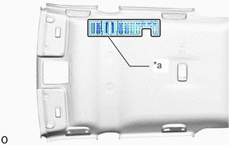
| *a | Marking |
Align the markings on the roof headlining assembly with the No. 1 roof headlining support and install them using hot-melt glue as shown in the illustration.
63362
25.INSTALL NO. 2 ROOF HEADLINING SUPPORT (for Normal Roof, for Korea)
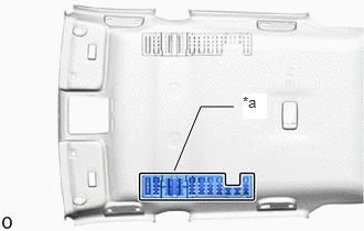
| *a | Marking |
Align the markings on the roof headlining assembly with the No. 2 roof headlining support and install them using hot-melt glue as shown in the illustration.
63352C
26.INSTALL ROOF HEADLINING PAD END (for Normal Roof)
Remove the release paper from 2 new roof headlining pad ends.
- HINT:
-
After removing the release paper, keep the exposed adhesive free from foreign matter.
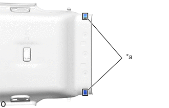
| *a | Marking |
Align the 2 roof headlining pad ends with the markings on the roof headlining assembly and install them as shown in the illustration.
63341
27.INSTALL NO. 1 ROOF SILENCER PAD (for Normal Roof)
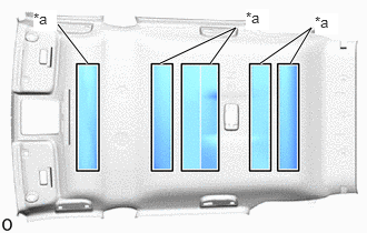
| *a | Marking |
Align 6 new No. 1 roof silencer pads with the silencer marking on the roof headlining assembly and install the 6 No. 1 roof silencer pads using hot-melt glue as shown in the illustration.
81340
28.INSTALL VANITY LIGHT ASSEMBLY
- HINT:
-
Use the same procedure for both vanity light assemblies.
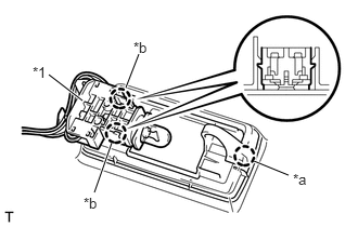
| *1 | Bulb Holder |
| *a | Claw A |
| *b | Claw B |
Attach claw A of the vanity light assembly to temporarily install the vanity light assembly to the roof headlining assembly.
Attach claw B of the bulb holder to install the vanity light assembly.