 |
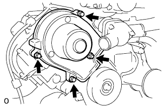
Remove the 3 bolts, nut and timing belt cover.
ENGINE UNIT > DISASSEMBLY |
| 1. REMOVE NO. 2 TIMING CHAIN OR BELT COVER |
|
Remove the 3 bolts, nut and timing belt cover.
| 2. REMOVE NO. 3 TIMING BELT COVER SUB-ASSEMBLY LH |
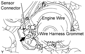 |
Separate the engine wire from the 4 wire clamps.
Disconnect the camshaft position sensor connector.
Disconnect the camshaft position sensor wire from the wire clamp on the timing belt cover.
Remove the wire harness grommet from the timing belt cover.
Remove the 4 bolts.
Pull the cover outward, pull the camshaft position sensor wire out of the cover, and remove the cover.
| 3. REMOVE NO. 2 TIMING BELT COVER SUB-ASSEMBLY |
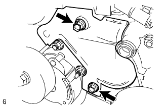 |
Remove the 2 bolts and timing belt cover.
| 4. REMOVE V-RIBBED BELT TENSIONER ASSEMBLY |
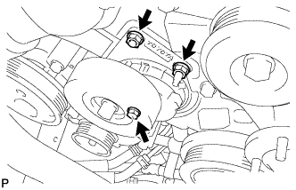 |
Remove the bolt, 2 nuts and V-ribbed belt tensioner.
| 5. REMOVE NO. 2 IDLER PULLEY SUB-ASSEMBLY |
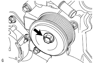 |
Remove the pulley bolt, cover plate and idler pulley.
| 6. REMOVE FAN BRACKET SUB-ASSEMBLY |
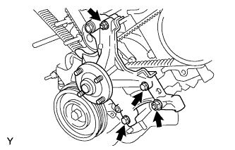 |
Remove the 2 nuts, 2 bolts and fan bracket.
| 7. REMOVE CRANKSHAFT DAMPER SUB-ASSEMBLY |
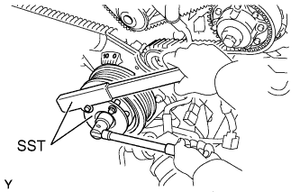 |
Using SST, remove the pulley set bolt.
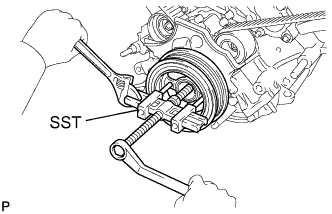 |
Using SST, remove the crankshaft damper sub-assembly.
| 8. REMOVE NO. 1 TIMING BELT COVER |
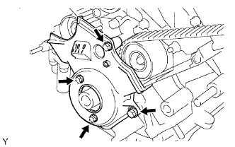 |
Remove the 4 bolts, timing belt cover, cover spacer and gasket.
| 9. REMOVE NO. 1 CRANKSHAFT POSITION SENSOR PLATE |
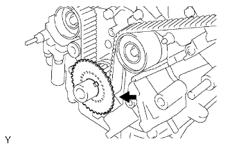 |
| 10. SET NO. 1 CYLINDER TO TDC/COMPRESSION |
Temporarily install the pulley set bolt.
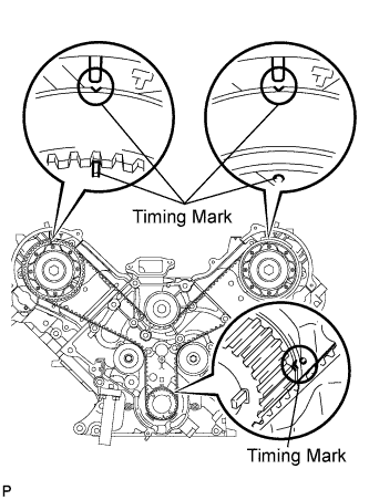 |
Rotate the crankshaft clockwise so that the timing marks on the crankshaft timing gear and camshaft timing gears are as shown in the illustration.
| 11. REMOVE TIMING BELT |
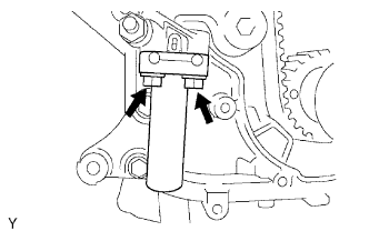 |
Alternately loosen the 2 bolts, and then remove the bolts, timing belt tensioner and dust boot.
Remove the timing belt.
| 12. REMOVE SPARK PLUG |
| 13. REMOVE OIL FILLER CAP SUB-ASSEMBLY |
| 14. REMOVE OIL FILLER CAP HOUSING |
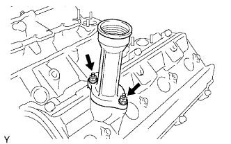 |
Remove the 2 nuts, housing and gasket.
| 15. REMOVE CYLINDER HEAD COVER SUB-ASSEMBLY LH |
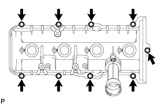 |
Remove the 9 bolts, cylinder head cover and gasket.
| 16. REMOVE CYLINDER HEAD COVER SUB-ASSEMBLY |
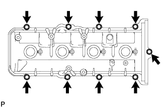 |
Remove the 9 bolts, cylinder head cover and gasket.
| 17. REMOVE CAMSHAFT POSITION SENSOR ASSEMBLY |
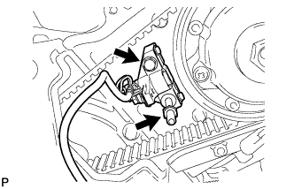 |
Remove the bolt, stud bolt and camshaft position sensor.
| 18. REMOVE REAR TIMING BELT PLATE LH |
Remove the 4 bolts, No. 2 timing belt plate and No. 1 timing belt plate.
| 19. REMOVE CAMSHAFT TIMING PULLEY SUB-ASSEMBLY LH |
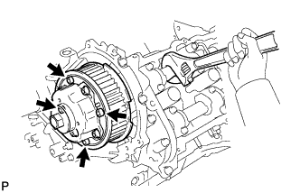 |
Hold the hexagonal portion of the camshaft with a wrench and remove the 4 bolts indicated by the arrows in the illustration and timing pulley.
| 20. REMOVE REAR TIMING BELT PLATE RH |
Remove the 4 bolts, No. 2 timing belt plate and No. 1 timing belt plate.
| 21. REMOVE CAMSHAFT TIMING PULLEY |
Hold the hexagonal portion of the camshaft with a wrench and remove the 4 bolts indicated by the arrows in the illustration and timing pulley.
| 22. REMOVE NO. 1 TIMING BELT IDLER SUB-ASSEMBLY |
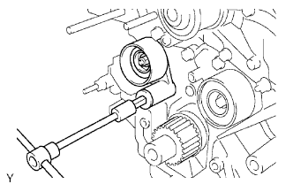 |
Using a 10 mm hexagon wrench, remove the bolt, idler and plate washer.
| 23. REMOVE NO. 2 TIMING BELT IDLER SUB-ASSEMBLY |
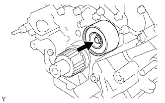 |
Remove the bolt and idler.
| 24. REMOVE CRANKSHAFT TIMING PULLEY |
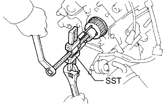 |
Using SST, remove the timing pulley.
| 25. REMOVE CAMSHAFT (for Bank 1) |
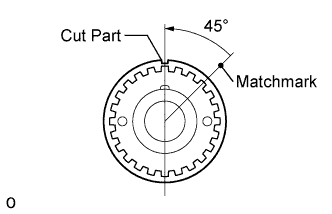 |
Check that the timing mark of the crankshaft timing pulley is in the position shown in the illustration, and that the piston is below the TDC of compression.
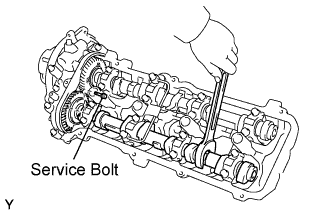 |
Bring the service bolt hole of the sub-gear upward by turning the hexagonal portion of the exhaust camshaft with a wrench.
Secure the sub-gear to the main gear with a service bolt.
| Thread Diameter | Thread Pitch | Bolt Length |
| 6.0 mm | 1.0 mm | 16 to 20 mm (0.630 to 0.787 in.) |
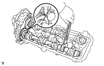 |
Using a wrench, turn the camshaft so that the timing marks (2 dot marks each) on the camshaft drive and driven main gears are aligned, as shown in the illustration.
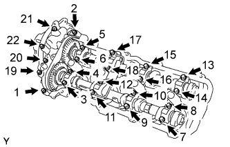 |
Uniformly loosen and remove the 22 bearing cap bolts in several steps, in the order shown in the illustration.
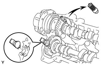 |
Remove the cap bolts, 4 seal washers, oil feed pipe, 9 bearing caps, camshaft housing plug, oil control valve filter and camshafts.
| 26. REMOVE CAMSHAFT (for Bank 2) |
|
Check that the timing mark of the crankshaft timing pulley is in the position shown in the illustration, and that the piston is below the TDC of compression.
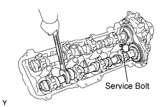 |
Bring the service bolt hole of the sub-gear upward by turning the hexagonal portion of the exhaust camshaft with a wrench.
Secure the sub-gear to the main gear with a service bolt.
| Thread Diameter | Thread Pitch | Bolt Length |
| 6.0 mm | 1.0 mm | 16 to 20 mm (0.630 to 0.787 in.) |
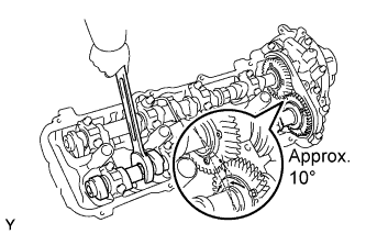 |
Using a wrench, turn the camshaft so that the timing marks (1 dot marks each) on the camshaft drive and driven main gears are aligned, as shown in the illustration.
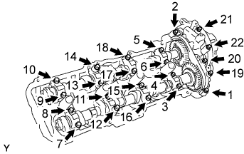 |
Uniformly loosen and remove the 22 bearing cap bolts in several steps, in the order shown in the illustration.
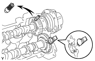 |
Remove the cap bolts, 4 seal washers, oil feed pipe, 9 bearing caps, camshaft housing plug, oil control valve filter and camshafts.
| 27. REMOVE VALVE LIFTER |
Remove the valve lifters and shims from the cylinder head.
| 28. REMOVE CYLINDER HEAD LH |
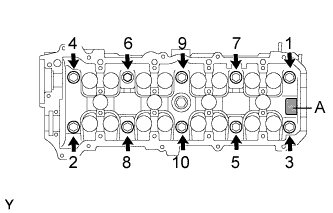 |
Uniformly loosen the 10 cylinder head bolts on the cylinder head in several passes, in the sequence shown in the illustration.
Remove the bolts and plate washers.
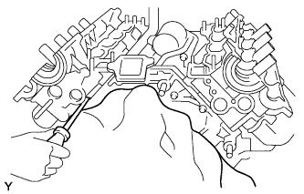 |
Remove the cylinder head by prying between the cylinder block and cylinder head with a screwdriver.
| 29. REMOVE NO. 2 CYLINDER HEAD GASKET |
| 30. REMOVE CYLINDER HEAD SUB-ASSEMBLY |
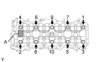 |
Uniformly loosen the 10 cylinder head bolts on the cylinder head in several passes, in the sequence shown in the illustration.
Remove the bolts and plate washers.
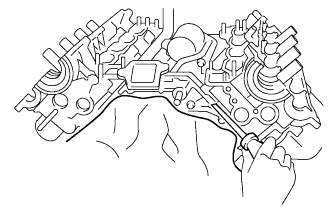 |
Remove the cylinder head by prying between the cylinder block and cylinder head with a screwdriver.
| 31. REMOVE CYLINDER HEAD GASKET |
| 32. REMOVE SPARK PLUG TUBE GASKET |
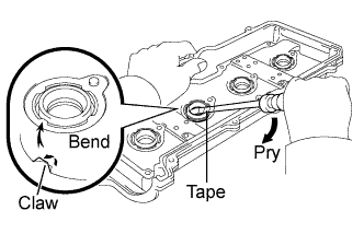 |
Bend the 8 ventilation case claws of the cylinder head cover to an angle of 90° or more.
Using a screwdriver, pry out the gaskets.
| 33. REMOVE CAMSHAFT TIMING TUBE ASSEMBLY |
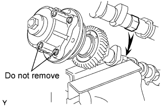 |
Mount the hexagonal portion of the camshaft in a vise.
Remove the screw plug and seal washer.
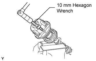 |
Using a 10 mm hexagon wrench, remove the bolt.
Pull out the timing tube and drive gear assembly from the camshaft.
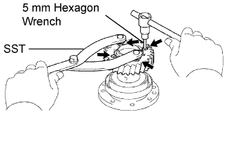 |
Using SST and a 5 mm hexagon wrench, remove the 4 bolts, drive gear and oil seal.
| 34. REMOVE CAMSHAFT SUB-GEAR |
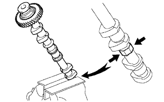 |
Mount the hexagonal portion of the camshaft in a vise.
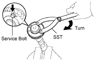 |
Using SST, turn the sub-gear clockwise, and remove the service bolt.
Using snap ring pliers, remove the snap ring.
Remove the wave washer, sub-gear and gear spring.
| 35. REMOVE CYLINDER BLOCK WATER DRAIN COCK SUB-ASSEMBLY |
Remove the 2 drain cocks.
Remove the 2 drain cock plugs.
| 36. REMOVE WATER PUMP ASSEMBLY |
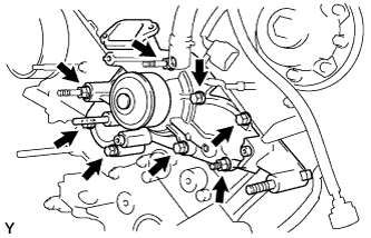 |
Remove the 5 bolts, 2 stud bolts, nut, water pump and gasket.
Remove the O-ring from the water by-pass pipe.
| 37. REMOVE OIL FILTER ASSEMBLY |
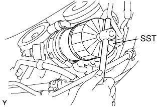 |
Using SST, remove the oil filter.
| 38. REMOVE OIL FILTER BRACKET SUB-ASSEMBLY |
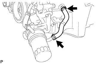 |
Disconnect the oil pressure sender gauge connector.
Disconnect the oil cooler hoses from the oil cooler.
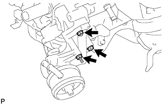 |
Remove the 2 bolts, nut and oil filter bracket.
| 39. REMOVE NO. 2 OIL PAN SUB-ASSEMBLY |
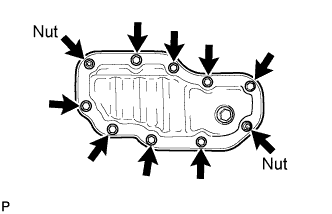 |
Remove the 8 bolts and 2 nuts.
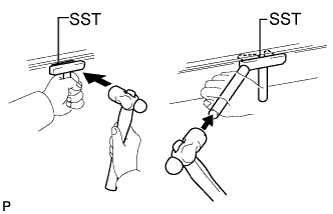 |
Insert the blade of SST between the oil pans, cut off applied sealer and remove the No. 2 oil pan.
| 40. REMOVE OIL PAN SUB-ASSEMBLY |
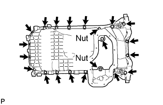 |
Remove the 18 bolts and 2 nuts.
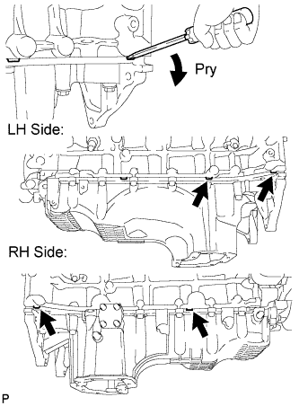 |
Using a screwdriver, remove the No. 1 oil pan by prying between the oil pan and cylinder block as shown in the illustration.
| 41. REMOVE NO. 1 OIL PAN BAFFLE PLATE |
Remove the 4 bolts and baffle plate.
| 42. REMOVE NO. 2 OIL PAN BAFFLE PLATE |
Remove the 4 bolts and baffle plate.
| 43. REMOVE NO. 3 OIL PAN BAFFLE PLATE |
Remove the 2 bolts and baffle plate.
| 44. REMOVE OIL STRAINER SUB-ASSEMBLY |
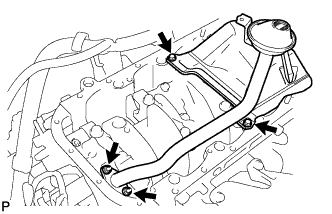 |
Remove the 2 bolts, 2 nuts, oil strainer and gasket.
| 45. REMOVE OIL PUMP ASSEMBLY |
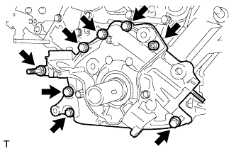 |
Remove the 7 bolts and 6 mm hexagon bolt.
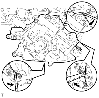 |
Using a screwdriver, remove the oil pump by prying the portions between the oil pump and cylinder block shown in the illustration.
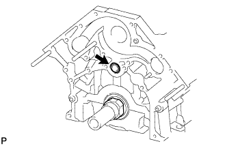 |
Remove the O-ring from the cylinder block.
| 46. REMOVE FRONT CRANKSHAFT OIL SEAL |
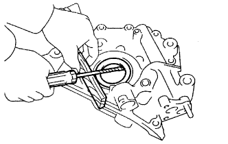 |
Place the oil pump on a wooden block.
Using a screwdriver and wooden block, pry out the oil seal.
| 47. REMOVE REAR ENGINE OIL SEAL RETAINER |
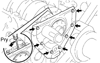 |
Remove the 7 bolts.
Using a screwdriver, remove the oil seal retainer by prying in between the oil seal retainer and crankshaft bearing cap.
Remove the O-ring.
| 48. REMOVE REAR CRANKSHAFT OIL SEAL |
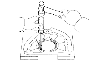 |
Place the rear oil seal retainer on wooden blocks.
Using a screwdriver and hammer, tap out the oil seal.