DTC P0505 Idle Control System Malfunction |
| DTC No. | DTC Detection Condition | Trouble Area |
| P0505 | Idling speed continues to vary greatly from target idling speed (2 trip detection logic) |
|
| Related DTCs | P0505: ISC function |
| Required Sensors/Components (Main) | ETCS |
| Required Sensors/Components (Related) | Crankshaft position sensor, Engine coolant temperature sensor, and Vehicle speed sensor |
| Frequency of Operation | Once per driving cycle |
| Duration | 10 minutes |
| MIL Operation | 2 driving cycles |
| Sequence of Operation | None |
| Monitor runs whenever following DTCs not present | P0010, P0020 (VVT Oil Control Valve) P0011, P0021 (VVT System - Advance) P0012, P0022 (VVT System - Retard) P0016, P0018 (VVT System - Misalignment) P0013, P0023 (Exhaust VVT Oil Control Valve) P0014, P0024 (Exhaust VVT System - Advance) P0015, P0025 (Exhaust VVT System - Retard) P0017, P0019 (Exhaust VVT System - Misalignment) P0031, P0032, P0051, P0052 (Air Fuel Ratio Sensor Heater) P2195, P2196, P2197, P2198, P2237, P2238, P2239, P2240, P2241, P2242, P2252, P2253, P2255, P2256, P2A00, P2A03 (Air Fuel Ratio Sensor) P0102, P0103 (Mass Air Flow Sensor) P0115, P0117, P0118 (Engine Coolant Temperature Sensor) P0125 (Insufficient Coolant Temperature for Closed Loop Fuel Control) P0120, P0121, P0122, P0123, P0220, P0222, P0223, P2135 (Throttle Position Sensor) P0171, P0172, P0174, P0175 (Fuel System) P0301 - P0308 (Misfire) P0335 (Crankshaft Position Sensor) P1340 (Camshaft Position Sensor) P0340, P0342, P0343, P0345, P0347, P0348 (VVT Sensor) P0365, P0367, P0368, P0390, P0392, P0393 (Exhaust VVT Sensor) P0351 - P0358 (Igniter) P0451, P0452, P0453 (EVAP System) P0500 (Vehicle Speed Sensor) P0705 (Shift Lever Position Switch) P0748, P0778 (Pressure Control Solenoid) P0973, P0974, P0976, P0977, P0979, P0980, P0982, P0983, P0985, P0986 (Shift Solenoid) |
| Engine | Running |
| Either of following conditions 1 or 2 met | - |
| 1. Frequency that both of following conditions (a) and (b) set | 5 times or more |
| (a) Engine speed - Target engine speed | Less than -100 rpm, or more than 150 rpm |
| (b) Vehicle condition | Stop after vehicle was driven at 10 km/h (6.25 mph) or more |
| 2. Frequency that both of following conditions (c) and (d) set | Once |
| (c) Engine speed - Target engine speed | Less than -100 rpm, or more than 150 rpm |
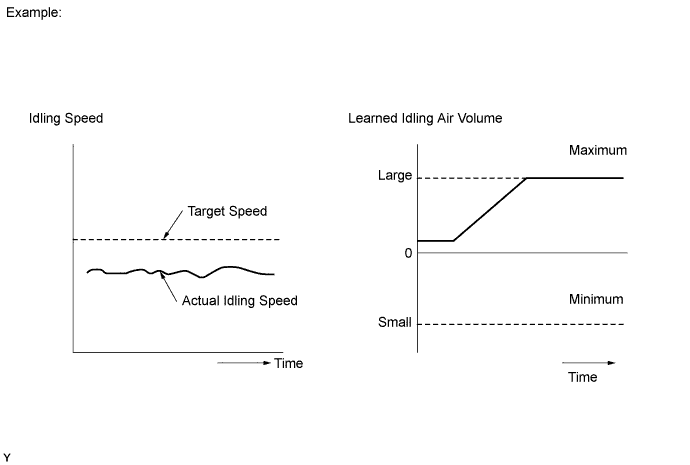
| (d) IAC flow rate learning value | 2.48 L/sec. or less, or 11.0 L/sec. or more |
| 1.CHECK ANY OTHER DTCS OUTPUT (IN ADDITION TO DTC P0505) |
Connect the Techstream to the DLC3.
Turn the ignition switch to ON.
Turn the Techstream on.
Enter the following menus: Powertrain / Engine and ECT / Trouble Codes.
Read DTCs.
| Result | Proceed to |
| P0505 is output | A |
| P0505 and other DTCs are output | B |
|
| ||||
| A | |
 |
| 2.CHECK PCV HOSE CONNECTIONS |
Check the PCV hose connections .
|
| ||||
| OK | |
|
| 3.CHECK AIR INDUCTION SYSTEM |
Check the air induction system for vacuum leak .
|
| ||||
| OK | |
|
| 4.INSPECT THROTTLE VALVE |
Check the throttle valve condition.
|
| ||||
| OK | ||
 | ||
| ||
