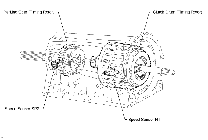
DTC P0717 Turbine Speed Sensor Circuit No Signal |
| DTC Code | DTC Detection Condition | Trouble Area |
| P0717 | All conditions below are detected for 5 seconds or more (1-trip detection logic) (a) Gear change is not performed (b) Gear position: 4th, 5th or 6th (c) T/M input shaft rpm: 300 rpm or less (d) T/M output shaft rpm: 1000 rpm or more (e) Park/neutral position switch:
|
|
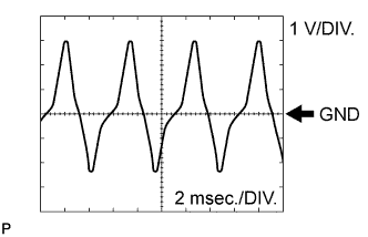
| Item | Content |
| Terminal No. (Symbol) | D56-124 (NT+) - D56-123 (NT-) |
| Tool setting | 1 V/DIV., 2 msec./DIV. |
| Condition | Engine is idling (Shift lever in P or N) |
| Related DTCs | P0717: Speed sensor (NT)/Verify pulse input |
| Required sensors/Components (Main) | Speed sensor (NT) |
| Required sensors/Components (Related) | Speed sensor (SP2) |
| Frequency of operation | Continuous |
| Duration | 5 seconds |
| MIL operation | Immediately |
| Sequence of operation | None |
| The monitor will run whenever the following DTCs are not present | P0705 (Park/neutral position switch circuit) P0751, P0973, P0974 (Shift solenoid valve S1) P0756, P0976, P0977 (Shift solenoid valve S2) P0761, P0979, P0980 (Shift solenoid valve S3) P0766, P0982, P0983 (Shift solenoid valve S4) P0748 (Shift solenoid valve SL1 circuit) P0776, P0778 (Shift solenoid valve SL2) |
| Shift change | After shift change is completed and before starting next shift change operation |
| ECM selected gear | 4th, 5th or 6th |
| Output shaft rpm | 1000 rpm or more |
| NSW switch | OFF |
| R switch | OFF |
| Engine | Running |
| Battery voltage | 8 V or more |
| Ignition switch | ON |
| Starter | OFF |
| Speed sensor signal rpm | Less than 300 rpm |
| Speed sensor signal rpm | 300 rpm or more |
| DATA LIST |
Warm up the engine.
Turn the ignition switch off.
Connect the Techstream to the DLC3.
Turn the ignition switch to ON.
Turn the Techstream on.
Enter the following menus: Powertrain / Engine and ECT / Data List.
According to the display on the Techstream, read the Data List.
| Tester Display | Measurement Item/Range | Normal Condition | Diagnostic Note |
| SPD (NT) | Input shaft speed/ Min.: 0 rpm Max.: 12750 rpm | Lock-up is:
| Data is displayed in increments of 50 rpm |
| 1.INSPECT SPEED SENSOR NT INSTALLATION |
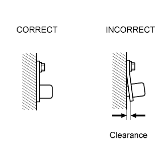 |
Check the speed sensor NT installation.
|
| ||||
| OK | |
 |
| 2.INSPECT SPEED SENSOR NT |
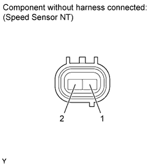 |
Disconnect the D43 speed sensor connector.
Measure the resistance according to the value(s) in the table below.
| Tester Connection | Condition | Specified Condition |
| 1 - 2 | 20°C (68°F) | 560 to 680 Ω |
|
| ||||
| OK | |
|
| 3.CHECK HARNESS AND CONNECTOR (SPEED SENSOR NT - ECM) |
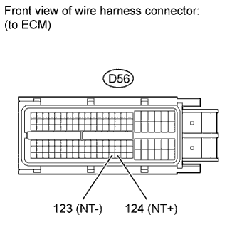 |
Disconnect the D56 ECM connector.
Measure the resistance according to the value(s) in the table below.
| Tester Connection | Condition | Specified Condition |
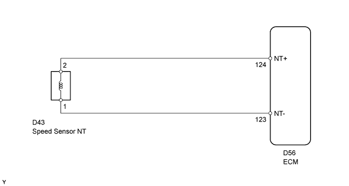
| D56-124 (NT+) - D56-123 (NT-) | 20°C (68°F) | 560 to 680 Ω |
| D56-124 (NT+) - Body ground | Always | 10 kΩ or higher |
| D56-123 (NT-) - Body ground | Always | 10 kΩ or higher |
| Result | Proceed to |
| NG | A |
| OK (for 3UR-FE) | B |
| OK (for 3UR-FBE) | C |
|
| ||||
|
| ||||
| A | ||
 | ||
| ||
