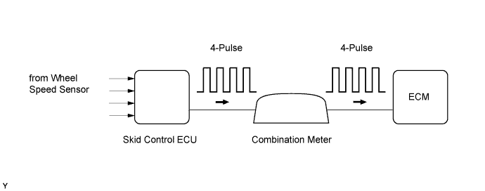
DTC P0500 Vehicle Speed Sensor "A" |
| DTC No. | DTC Detection Condition | Trouble Area |
| P0500 | While vehicle being driven, no vehicle speed sensor signal transmitted to ECM (2 trip detection logic) |
|
| Related DTCs | P0500: Vehicle speed sensor "A" pulse input error |
| Required Sensors/Components (Main) | Vehicle Speed Sensor (VSS), Combination meter and Skid control ECU |
| Required Sensors/Components (Related) | Park/Neutral Position (PNP) switch, Engine Coolant Temperature (ECT) sensor, Crankshaft Position (CKP) sensor, Throttle Position (TP) sensor and Mass Air Flow (MAF) meter |
| Frequency of Operation | Continuous |
| Duration | 5 seconds |
| MIL Operation | 2 driving cycles |
| Sequence of Operation | None |
| Monitor runs whenever following DTCs not present | None |
| Time after ignition switch off to ON | 3 seconds or more |
| Transfer neutral switch* | Not "N" position |
| Vehicle speed | 9 km/h (5.59 mph) or more |
| Battery voltage | 8 V or more |
| Starter | OFF |
| Vehicle speed sensor signal | No pulse input |
| 1.CHECK OPERATION OF SPEEDOMETER |
Drive the vehicle and check whether the operation of the speedometer in the combination meter is normal.
|
| ||||
| OK | |
 |
| 2.READ VALUE USING TECHSTREAM (VEHICLE SPD) |
Connect the Techstream to the DLC3.
Turn the ignition switch to ON.
Turn the Techstream on.
Enter the following menus: Powertrain / Engine and ECT / Data List / All Data / Vehicle Speed.
Drive the vehicle.
Read the value displayed on the Techstream.
|
| ||||
| OK | ||
 | ||
| ||
| 3.INSPECT COMBINATION METER ASSEMBLY (+S VOLTAGE) |
 |
Disconnect the combination meter connector.
Turn the ignition switch to ON.
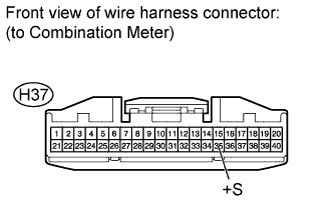
Measure the voltage according to the value(s) in the table below.
| Tester Connection | Switch Condition | Specified Condition |
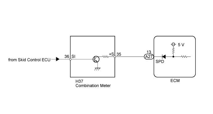
| H37-35 (+S) - Body ground | Ignition switch ON | 4.5 to 5.5 V |
|
| ||||
| OK | |
|
| 4.INSPECT COMBINATION METER ASSEMBLY (SPD SIGNAL WAVEFORM) |
 |
Move the shift lever to N.
Jack up the vehicle.
Turn the ignition switch to ON.
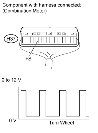
Measure the voltage according to the value(s) in the table below.
| Tester Connection | Switch Condition | Specified Condition |
| H37-35 (+S) - Body ground |
| Voltage generated intermittently |
|
| ||||
| OK | |
|
| 5.CHECK HARNESS AND CONNECTOR (COMBINATION METER - ECM) |
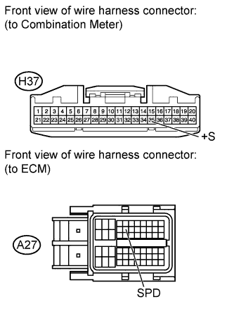 |
Disconnect the combination meter connector.
Disconnect the ECM connector.
Measure the resistance according to the value(s) in the table below.
| Tester Connection | Condition | Specified Condition |
| H37-35 (+S) - A27-13 (SPD) | Always | Below 1 Ω |
| H37-35 (+S) or A27-13 (SPD) - Body ground | Always | 10 kΩ or higher |
|
| ||||
| OK | ||
| ||
| ||

