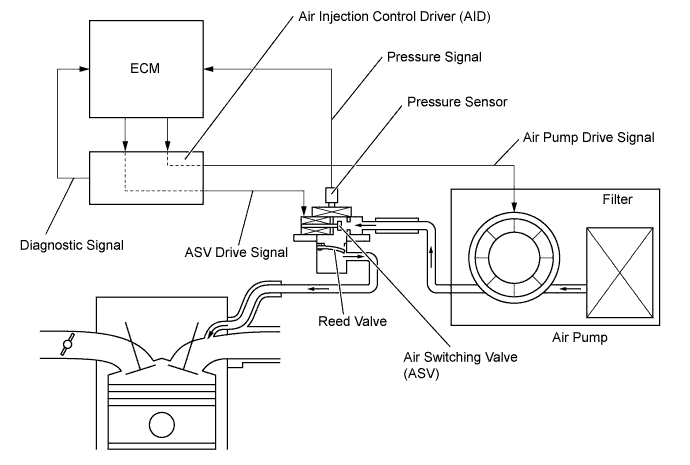
DTC P2431 Secondary Air Injection System Air Flow / Pressure Sensor Circuit Range / Performance Bank1 |
DTC P2432 Secondary Air Injection System Air Flow / Pressure Sensor Circuit Low Bank1 |
DTC P2433 Secondary Air Injection System Air Flow / Pressure Sensor Circuit High Bank1 |
DTC P2436 Secondary Air Injection System Air Flow / Pressure Sensor Circuit Range / Performance Bank 2 |
DTC P2437 Secondary Air Injection System Air Flow / Pressure Sensor Circuit Low Bank 2 |
DTC P2438 Secondary Air Injection System Air Flow / Pressure Sensor Circuit High Bank 2 |
| DTC No. | DTC Detection Condition | Trouble Area |
| P2431 P2436 | Pressure sensor indicates less than 45.6 kPa (342 mmHg), or more than 135 kPa (1013 mmHg) (2 trip detection logic) |
|
| P2432 P2437 | While engine running, voltage output of pressure sensor remains below 0.5 V (1 trip detection logic) |
|
| P2433 P2438 | While engine running, voltage output of pressure sensor remains above 4.5 V (1 trip detection logic) |
|
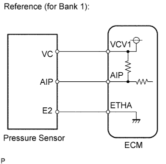
| Related DTCs | P2431: Air flow/Pressure sensor circuit rationality P2432: Air flow/Pressure sensor circuit range check (Low voltage) P2433: Air flow/Pressure sensor circuit range check (High voltage) P2436: Air flow/Pressure sensor circuit rationality P2437: Air flow/Pressure sensor circuit range check (Low voltage) P2438: Air flow/Pressure sensor circuit range check (High voltage) |
| Required Sensors/Components (Main) | Pressure sensor |
| Required Sensors/Components (Related) | - |
| Frequency of Operation | Continuous |
| Duration | P2432, P2433, P2437, P2438: 0.5 seconds P2431, P2436: 5 seconds |
| MIL Operation | P2432, P2433, P2437, P2438: Immediate P2431, P2436: 2 driving cycles |
| Sequence of Operation | None |
| Monitor runs whenever following DTCs not present | None |
| All of following conditions met: | - |
| Starter | OFF |
| Battery voltage | 8 V or more |
| Ignition switch | ON |
| Monitor runs whenever following DTCs not present | P2432, P2433, P2437, P2438 (Secondary Air Injection System Pressure Sensor) |
| Starter | OFF |
| Battery voltage | 8 V or more |
| Ignition switch | ON |
| Air pressure sensor voltage | Less than 0.5 V |
| Air pressure sensor voltage | More than 4.5 V |
| Air pressure | Less than 45.63 kPa (342 mmHg), or more than 135 kPa (1013 mmHg) |
| Air pressure sensor voltage | Between 0.5 V and 4.5 V |
| 1.CHECK HARNESS AND CONNECTOR (PRESSURE SENSOR - ECM) |
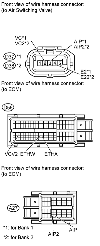 |
Disconnect the pressure sensor connector.
Disconnect the ECM connectors.
Measure the resistance according to the value(s) in the table below.
| Tester Connection | Condition | Specified Condition |
| D37-3 (AIP) - A27-54 (AIP) | Always | Below 1 Ω |
| D37-2 (VC) - D56-67 (VCV1) | Always | Below 1 Ω |
| D37-4 (E2) - D56-98 (ETHA) | Always | Below 1 Ω |
| D38-3 (AIP2) - A27-53 (AIP2) | Always | Below 1 Ω |
| D38-2 (VC2) - D56-67 (VCV1) | Always | Below 1 Ω |
| D38-4 (E22) - D56-97 (ETHW) | Always | Below 1 Ω |
| D37-3 (AIP) or A27-54 (AIP) - Body ground | Always | 10 kΩ or higher |
| D37-2 (VC) or D56-67 (VCV1) - Body ground | Always | 10 kΩ or higher |
| D38-3 (AIP2) or A27-53 (AIP2) - Body ground | Always | 10 kΩ or higher |
| D38-2 (VC2) or D56-67 (VCV1) - Body ground | Always | 10 kΩ or higher |
|
| ||||
| OK | |
 |
| 2.INSPECT AIR SWITCHING VALVE (PRESSURE SENSOR) |
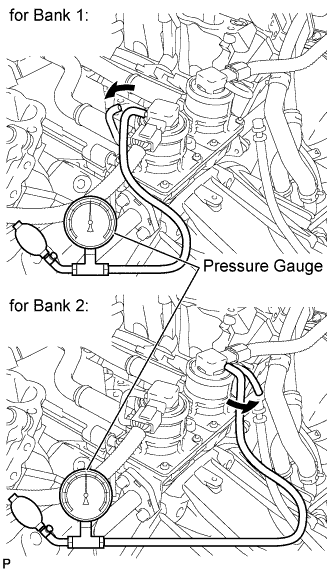 |
Connect a pressure gauge to the air pressure sensor as shown in the illustration.
Connect the Techstream to the DLC3.
Turn the ignition switch to ON.
Turn the Techstream on.
Enter the following menus: Powertrain / Engine and ECT / Data List / Air pump pressure (absolute) and Air Pump2 Pressure (Absolute).
Check that the pressure displayed on the Techstream fluctuates when applying the pressure to the pressure sensor with the pressure gauge.
|
| ||||
| OK | ||
 | ||
| ||
