 |
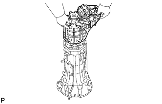
Install the transfer with the 8 bolts.
- Torque:
- 40 N*m{ 408 kgf*cm , 30 ft.*lbf }
- NOTICE:
- Take care not to damage the rear adaptor oil seal with the transfer input gear spline.
AUTOMATIC TRANSMISSION ASSEMBLY > INSTALLATION |
| 1. INSTALL TRANSFER ASSEMBLY |
|
Install the transfer with the 8 bolts.
| 2. INSTALL TORQUE CONVERTER ASSEMBLY |
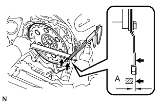 |
Using a vernier caliper and straightedge, measure dimension A between the transmission fitting surface of the engine and the converter fitting surface of the drive plate.
Install the torque converter to the transmission housing.
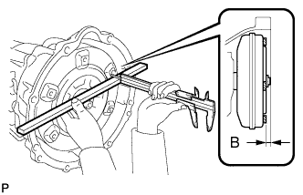 |
Using a vernier caliper and straightedge, measure dimension B shown in the illustration and check that B is greater than A measured in the first step.
| 3. INSTALL TRANSMISSION CONTROL CABLE BRACKET |
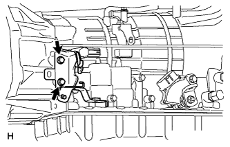 |
Install the transmission control cable bracket with the 2 bolts.
| 4. INSTALL CONNECTOR CLAMP BRACKET |
Install the front left bank oxygen sensor connector clamp bracket with the bolt.
Install the rear left bank oxygen sensor connector clamp bracket with the bolt.
| 5. INSTALL AUTOMATIC TRANSMISSION ASSEMBLY |
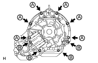 |
Install the automatic transmission assembly with the 10 bolts.
| 6. CONNECT WIRE HARNESS AND CONNECTOR |
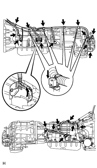 |
Connect the park/neutral position switch connector, transmission wire connector, 2 transmission revolution sensor connectors and 3 transfer control side connectors.
Connect the harness clamp with the bolt.
Connect the 4 connector clamps and 8 harness clamps.
Tilt up the automatic transmission.
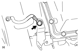 |
Connect the ground cable with the bolt.
| 7. INSTALL REAR NO. 1 ENGINE MOUNTING INSULATOR |
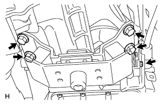 |
Install the rear No. 1 engine mounting insulator to the transmission with the 4 bolts.
Install the rear engine mounting heat insulator with the bolt.
| 8. INSTALL NO. 3 FRAME CROSSMEMBER SUB-ASSEMBLY |
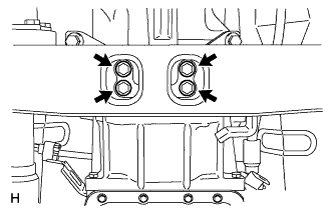 |
Install the No. 3 frame crossmember to the rear engine mounting insulator with the 4 bolts.
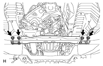 |
Install the No. 3 frame crossmember with the 4 bolts, 4 washers and 4 nuts.
| 9. INSTALL DRIVE PLATE AND TORQUE CONVERTER CLUTCH SETTING BOLT |
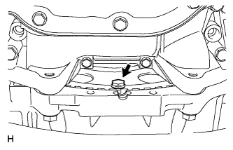 |
Turn the crankshaft to gain access to the 6 bolts and install the bolt while holding the crankshaft pulley setting bolt with a wrench.
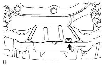 |
Install the flywheel housing under cover with the bolt.
| 10. CONNECT TRANSMISSION CONTROL CABLE ASSEMBLY |
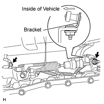 |
Connect the transmission control cable with a new clip and nut.
| 11. INSTALL TRANSMISSION OIL COOLER ASSEMBLY (w/o Trailer Towing System) |
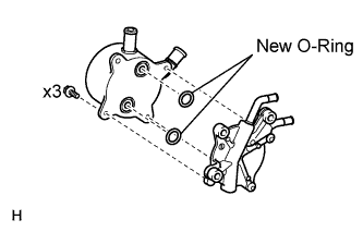 |
Coat 2 new O-rings with ATF, and install them to the transmission oil cooler.
Align the transmission oil cooler with the transmission oil cooler spacer and assemble them with the 3 bolts.
Connect the 2 transmission oil cooler hoses to the transmission oil cooler spacer with the 2 clips.
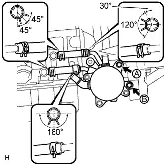 |
Temporarily install the transmission oil cooler with transmission oil thermostat with bolt A.
Install the bolt B and tighten it to the specified torque. Then tighten bolt A to the specified torque.
Connect the 2 transmission oil cooler hoses with the 2 clips.
| 12. INSTALL TRANSMISSION OIL COOLER ASSEMBLY (w/ Trailer Towing System) |
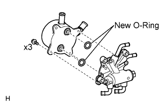 |
Coat 2 new O-rings with ATF, and install them to the transmission oil cooler.
Align the transmission oil cooler with the transmission oil thermostat and assemble them with the 3 bolts.
Connect the 2 transmission oil cooler hoses to the transmission oil thermostat with the 2 clips.
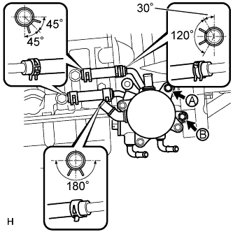 |
Temporarily install the transmission oil cooler with transmission oil thermostat with bolt A.
Install the bolt B and tighten it to the specified torque. Then tighten bolt A to the specified torque.
Connect the 2 transmission oil cooler hoses with the 2 clips.
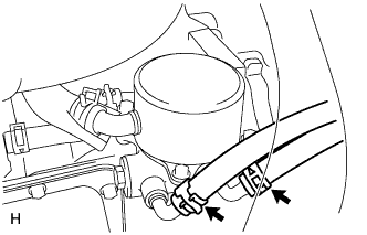 |
Connect the 2 No. 2 transmission oil cooler hoses to the transmission oil thermostat.
| 13. CONNECT WATER BY-PASS PIPE ASSEMBLY |
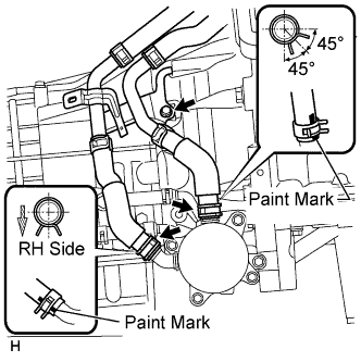 |
Connect the 2 water by-pass hoses with the 2 clips and install the water by-pass pipe with the bolt.
| 14. INSTALL HOSE HEAT PROTECTOR |
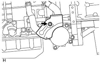 |
Install the hose heat protector with the bolt.
| 15. INSTALL FRONT NO. 3 EXHAUST PIPE ASSEMBLY |
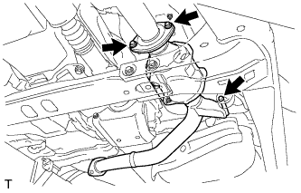 |
Install the new gasket to the front No. 2 exhaust pipe assembly.
Connect the front No. 3 exhaust pipe sub-assembly to the exhaust pipe support.
Install the front No. 3 exhaust pipe sub-assembly with the 2 bolts and 2 nuts.
| 16. INSTALL FRONT EXHAUST PIPE ASSEMBLY |
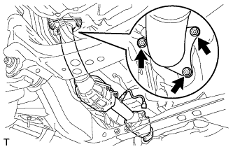 |
Install the new gasket to the front exhaust pipe assembly.
Install the front exhaust pipe assembly with the 3 new nuts.
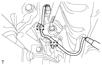 |
Connect the heated oxygen sensor connector.
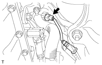 |
Connect the air fuel ratio sensor connector.
| 17. INSTALL PROPELLER SHAFT ASSEMBLY |
Install the propeller shaft assembly (Click here).
| 18. INSTALL FRONT PROPELLER SHAFT ASSEMBLY |
Install the front propeller shaft assembly (Click here).
| 19. ADD ENGINE COOLANT |
Add engine coolant.
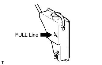 |
Slowly pour coolant into the radiator reservoir until it reaches the FULL line.
Install the reservoir cap.
Press the inlet and outlet radiator hoses several times by hand, and then check the coolant level. If the coolant level is low, add coolant.
Install the radiator cap.
Start the engine and warm it up until the thermostat opens.
Maintain the engine speed at 2000 to 2500 rpm and warm up the engine until the cooling fan operates.
Press the inlet and outlet radiator hoses several times by hand to bleed air.
Stop the engine, and wait until the engine coolant cools down.
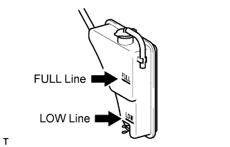 |
If the coolant level is below the LOW line, repeat all of the procedures above.
| 20. ADD TRANSFER OIL |
Install a new gasket and the drain plug.
Pour oil so that the oil level is between 0 to 5.0 mm (0 to 0.197 in.) from the bottom lip of the filler plug hole.
Wait approximately 5 minutes and check that the oil level has not changed.
Install a new gasket and the filler plug.
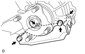 |
Install the lower transfer case protector with the 4 bolts.
| 21. ADD AUTOMATIC TRANSMISSION FLUID |
| Repair | Fill amount |
| Transmission pan and drain plug removal | 1.7 liters (1.8 US qts, 1.5 Imp. qts) |
| Transmission valve body removal | 4.3 liters (4.5 US qts, 3.8 Imp. qts) |
| Torque converter removal | 5.4 liters (5.7 US qts, 4.8 Imp. qts) |
| 22. ADJUST AUTOMATIC TRANSMISSION FLUID |
Adjust automatic transmission fluid (Click here).
| 23. INSPECT FOR AUTOMATIC TRANSMISSION FLUID LEAK |
| 24. INSPECT FOR TRANSFER OIL LEAK |
| 25. INSPECT FOR ENGINE COOLANT LEAK |
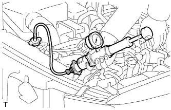 |
Fill the radiator with coolant and attach a radiator cap tester.
Warm up the engine.
Using the radiator cap tester, increase the pressure inside the radiator to 118 kPa (1.2 kgf/cm2, 17 psi), and check that the pressure does not drop. If the pressure drops, check the hoses, radiator and water pump for leaks. If no external leaks are found, check the heater core, cylinder block and head.
| 26. INSPECT FOR EXHAUST GAS LEAK |
| 27. INSPECT SHIFT LEVER POSITION |
When moving the shift lever from P to R with the ignition switch ON and the brake pedal depressed, make sure that it moves smoothly and correctly into position.
Check that the shift lever does not stop when moving the shift lever from R to P, and check that the shift lever does not stick when moving the shift lever from D to S.
Start the engine and make sure that the vehicle moves forward after moving the shift lever from N to D and moves rearward after moving the shift lever to R.
If the operation cannot be done as specified, inspect the park/neutral position switch assembly and check the shift lever assembly installation condition.
| 28. ADJUST SHIFT LEVER POSITION |
Move the shift lever to N.
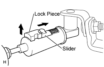 |
Fold back the transmission control cable adjust case cover. Then while sliding the slider toward the cable end side, press the lock piece from the back side to release the lock.
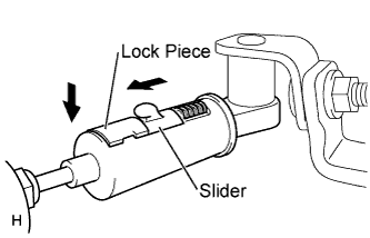 |
Check that the adjust case's spring is applying enough tension to the shift control cable. Then press the lock piece to set the lock.
Return the cover of the adjust case to its original position.
Inspect the operation after the adjustment.
| 29. RESET MEMORY |
Perform the Reset Memory procedures (A/T initialization) (Click here).