 |
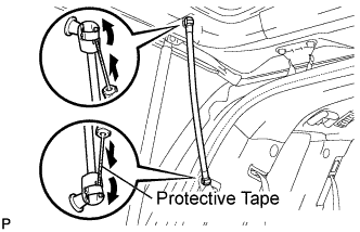
Using a screwdriver with its tip wrapped in protective tape, remove the 2 stop rings and power back door rod.
BACK DOOR > DISASSEMBLY |
| 1. DISCONNECT CABLE FROM NEGATIVE BATTERY TERMINAL |
| 2. REMOVE POWER BACK DOOR ROD (w/ Power Back Door) |
|
Using a screwdriver with its tip wrapped in protective tape, remove the 2 stop rings and power back door rod.
| 3. REMOVE BACK DOOR CENTER GARNISH |
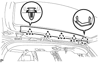 |
Disengage the 4 clips and the claw and remove the back door center garnish.
| 4. REMOVE BACK DOOR SIDE GARNISH RH |
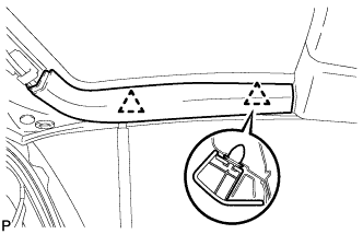 |
Disengage the 2 clips and remove the back door side garnish RH.
| 5. REMOVE BACK DOOR SIDE GARNISH LH |
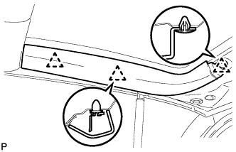 |
Disengage the 3 clips and remove the back door side garnish LH
| 6. REMOVE BACK DOOR STAY LOWER BRACKET (w/ Power Back Door) |
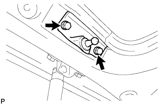 |
Remove the 2 bolts and remove the back door stay lower bracket.
| 7. REMOVE BACK DOOR STRAP COVER |
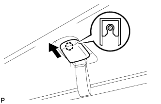 |
Slide the back door strap cover and disengage the claw and remove the back door strap cover.
| 8. REMOVE BACK DOOR PULL STRAP |
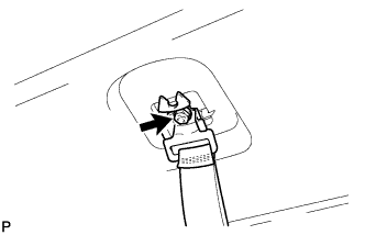 |
Remove the bolt and remove the back door pull strap.
| 9. REMOVE BACK DOOR TRIM BOARD ASSEMBLY |
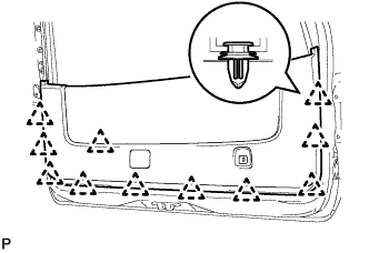 |
Disengage the 11 clips and remove the back door trim board assembly.
| 10. REMOVE BACK DOOR GLASS WEATHERSTRIP |
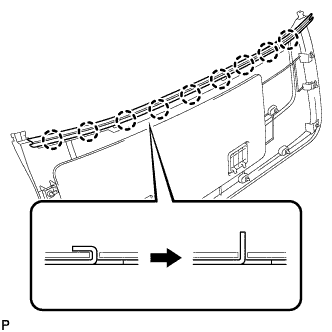 |
Raise the 9 claws of the rear back door glass weatherstrip and then remove the back door glass weatherstrip from the back door trim board assembly, as shown in the illustration.
| 11. REMOVE BACK DOOR SERVICE HOLE COVER |
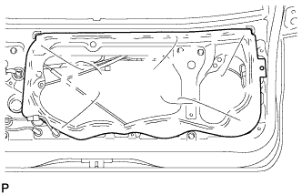 |
Remove the back door service hole cover.
| 12. REMOVE POWER BACK DOOR WARNING BUZZER (w/ Power Back Door) |
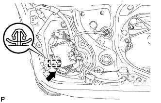 |
Disconnect the connector.
Disengage the clamp and remove the power back door warning buzzer.
| 13. REMOVE MULTIPLEX NETWORK BODY ECU (w/ Power Back Door) |
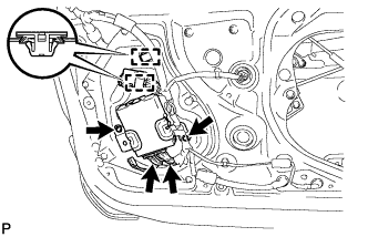 |
Disconnect the 2 connectors and disengage the 2 clamps.
Remove the 2 screws and remove the multiplex network body ECU.
| 14. REMOVE BACK DOOR NO. 2 SERVICE HOLE COVER |
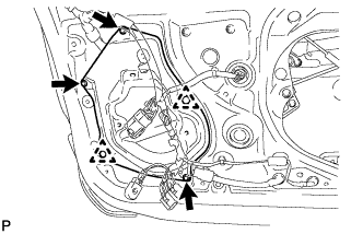 |
Remove the 3 screws and disengage the 2 clips and remove the back door No. 2 service hole cover.
| 15. REMOVE POWER BACK DOOR SENSOR RH |
Disconnect the connector.
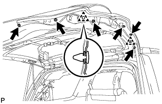 |
Remove the 6 screws.
Disengage the 2 clips and remove the power back door sensor.
| 16. REMOVE POWER BACK DOOR SENSOR LH |
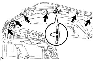 |
Disconnect the connector.
Remove the 6 screws.
Disengage the 2 clips and remove the power back door sensor assembly.
| 17. REMOVE REAR WIPER ARM HEAD CAP |
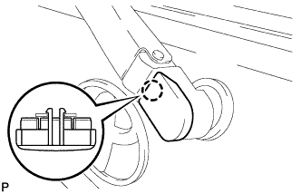 |
Disengage the claw and remove the rear wiper arm head cap.
| 18. REMOVE REAR WIPER BLADE ASSEMBLY |
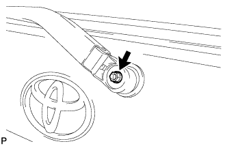 |
Remove the nut and remove the rear wiper blade assembly.
| 19. REMOVE REAR WIPER MOTOR ASSEMBLY |
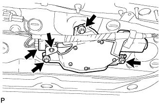 |
Disengage the clamp and disconnect the connector.
Loosen the 3 bolts and remove the rear wiper motor.
| 20. REMOVE REAR WIPER MOTOR GROMMET |
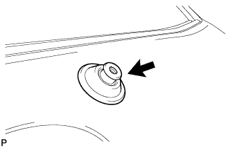 |
Remove the rear wiper motor grommet.
| 21. REMOVE LINEAR WIPER STEP RH |
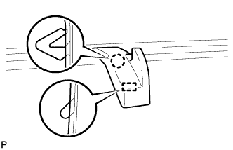 |
Disengage the claw and guide and remove the linear wiper step RH
| 22. REMOVE BACK DOOR OUTSIDE MOULDING LH |
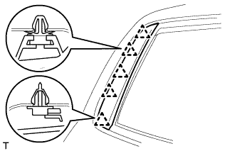 |
Disengage the 5 clips and remove the back door outside moulding.
| 23. REMOVE BACK DOOR OUTSIDE MOULDING RH |
| 24. REMOVE BACK DOOR GLASS OUTER WEATHERSTRIP ASSEMBLY |
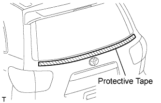 |
Apply protective tape to the door panel in the area around the back door glass outer weatherstrip.
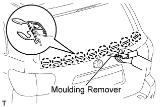 |
Using a moulding remover, disengage the 9 claws and remove the back door glass outer weatherstrip.
| 25. REMOVE BACK DOOR GLASS RUN |
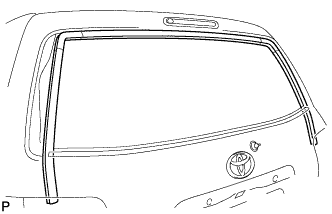 |
Remove the back door glass run.
| 26. REMOVE BACK DOOR GLASS |
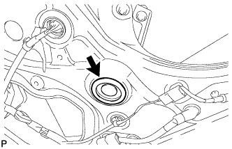 |
Remove the hole plig.
Provisionally install the multiplex network body ECU.
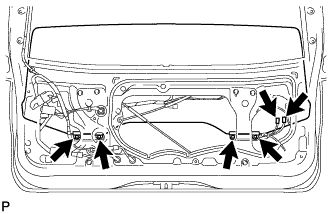 |
Move the back door glass until the 4 bolts can be seen through the service holes.
Disconnect the 2 connectors.
Remove the 4 bolts and remove the back door glass.
Remove the multiplex network body ECU.
| 27. REMOVE BACK DOOR POWER WINDOW REGULATOR ASSEMBLY |
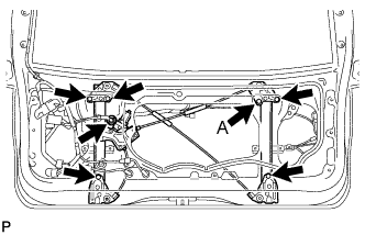 |
Disconnect the connector.
Loosen nut A.
Remove the 5 nuts, then remove the back door power window regulator assembly.
| 28. REMOVE BACK DOOR LOCK CYLINDER |
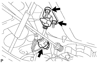 |
Disconnect the connector
Remove the 2 nuts and remove the back door lock cylinder.
| 29. REMOVE BACK DOOR OUTSIDE GARNISH |
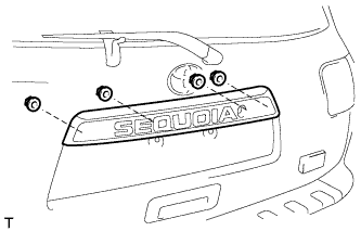 |
Remove the 4 nuts.
Disconnect the connector.
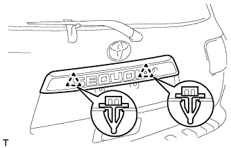 |
Disengage the 2 clips and remove the back door outside garnish.
| 30. REMOVE REAR TELEVISION CAMERA ASSEMBLY |
Remove the 2 nuts.
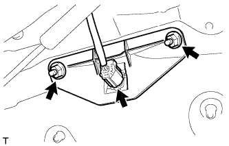 |
Disconnect the connector.
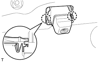 |
Disengage the 2 claws and remove the rear television camera.
| 31. REMOVE LICENSE PLATE LIGHT ASSEMBLY |
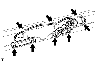 |
Remove the 4 screws.
Disconnect the 4 harness clamps and remove the license plate light.
| 32. REMOVE BACK DOOR OUTSIDE HANDLE |
Disconnect the connector.
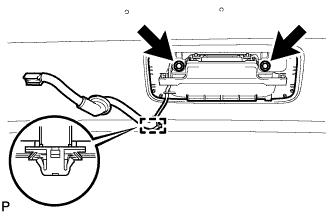 |
Disengage the clamp.
Remove the 2 bolts and remove the back door outside handle.
| 33. REMOVE BACK DOOR LOCK PROTECTOR |
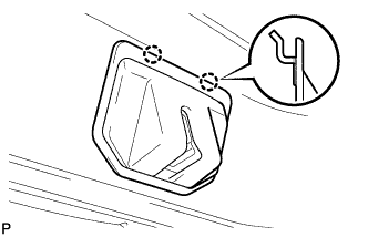 |
Disengage the 2 claws and back door lock protector sub-assembly.
| 34. REMOVE BACK DOOR LOCK (w/o Power Back Door) |
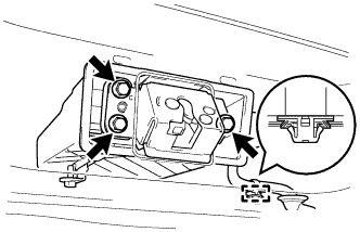 |
Disconnect the connector.
Disengage the clamp.
Remove the 3 bolts and back door lock.
| 35. REMOVE BACK DOOR LOCK (w/ Power Back Door) |
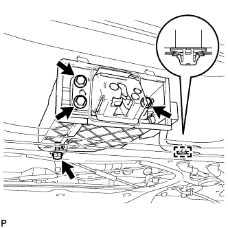 |
Disconnect the connector.
Disengage the clamp.
Remove the 4 bolts and back door lock.
| 36. REMOVE REAR LIGHT ASSEMBLY RH |
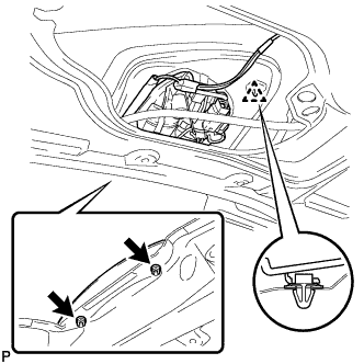 |
Disconnect the connector.
Remove the 2 nuts.
Disengage the clip and remove the rear light.
| 37. REMOVE REAR LIGHT ASSEMBLY LH |
|
Disconnect the connector.
Remove the 2 nuts.
Disengage the clip and remove the rear light.
| 38. REMOVE REAR SPOILER COVER |
Disconnect the connector.
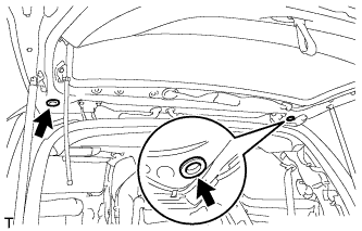 |
Remove the 2 hole plugs.
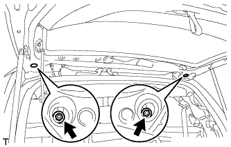 |
Remove the 2 nuts.
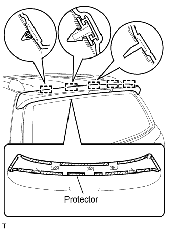 |
Disengage the 5 pins and remove the rear spoiler.