 |
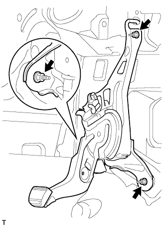
Install the control pedal to the body with the 3 nuts.
- Torque:
- 13 N*m{ 128 kgf*cm , 9 ft.*lbf }
PARKING BRAKE PEDAL > INSTALLATION |
| 1. INSTALL PARKING BRAKE CONTROL PEDAL ASSEMBLY |
|
Install the control pedal to the body with the 3 nuts.
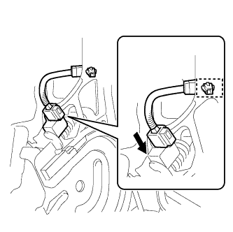 |
Attach the wire harness clamp to the control pedal.
Connect the parking brake switch connector.
| 2. CONNECT NO. 1 PARKING BRAKE CABLE ASSEMBLY |
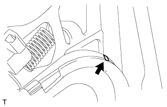 |
Connect the parking brake cable to the control pedal.
Using needle-nose pliers, slowly bend down the claw.
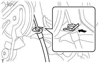 |
Install a new clip to the control pedal.
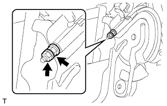 |
Temporarily install the adjustment nut and lock nut.
| 3. CHECK PARKING BRAKE PEDAL TRAVEL |
Firmly depress the parking brake pedal.
Release the parking brake.
Slowly depress the parking brake pedal with a force of approximately 300 N (31 kgf, 67.4 lbf) and count the number of clicks.
| 4. ADJUST PARKING BRAKE PEDAL TRAVEL |
Depress the parking brake pedal.
Release the parking brake pedal to the original position.
|
Loosen the pedal side No. 1 parking brake cable lock nut.
Turn the pedal side No. 1 parking brake cable adjustment nut until the parking brake pedal travel is correct.
| Pedal Load | Click Number |
| 300 N (31 kgf, 67.4 lbf) | 6 to 9 |
Using a wrench or equivalent to hold the adjustment nut, tighten the lock nut.
Additionally, excessive pedal travel can be adjusted on the No. 1 parking brake cable underbody side as follows.
Release the parking brake pedal to the original position.
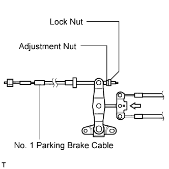 |
Loosen the underbody side No. 1 parking brake cable lock nut.
Turn the underbody side No. 1 parking brake cable adjustment nut until the parking brake pedal travel is correct.
| Pedal Load | Click Number |
| 300 N (31 kgf, 67.4 lbf) | 6 to 9 |
Tighten the No. 1 parking brake cable underbody lock nut.
Depress to full stroke and release the parking brake pedal 3 or 4 times. Then check the number of clicks when depressing the pedal.
Check whether the parking brake drags or not.
If the parking brake drags, adjust the shoe clearance.
When operating the parking brake pedal, check that the parking brake pedal indicator light comes on at the first notch.
If not, adjust the parking brake switch installation position.
| 5. INSTALL NO. 1 INSTRUMENT PANEL SAFETY PAD INSERT |
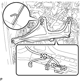 |
Connect the connector and engage the clamp.
Engage the 2 claws to install the safety pad insert.
Install the 4 <A> bolts.
| 6. INSTALL LOWER INSTRUMENT PANEL FINISH PANEL SUB-ASSEMBLY LH |
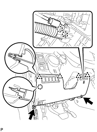 |
Engage the 2 claws and install the sensor.
Connect the connectors.
Engage the 4 clips and claw and install the finish panel.
Install the 2 <A> bolts.
| 7. INSTALL HOOD LOCK CONTROL LEVER SUB-ASSEMBLY |
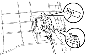 |
Connect the hood lock control cable assembly to the hood lock control lever sub-assembly.
engage the 3 claws to install the hood lock lever
| 8. INSTALL INSTRUMENT SIDE PANEL LH |
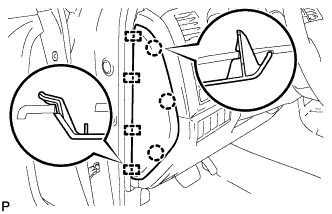 |
Engage the 4 guides and 3 claws and install the side panel.
| 9. INSTALL COWL SIDE TRIM BOARD LH |
| 10. INSTALL FRONT DOOR SCUFF PLATE LH |