 |
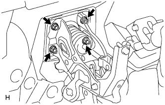
Install the brake booster with the 4 nuts.
- Torque:
- 15 N*m{ 155 kgf*cm , 11 ft.*lbf }
BRAKE BOOSTER > INSTALLATION |
| 1. INSTALL BRAKE VACUUM CHECK VALVE ASSEMBLY |
| 2. INSTALL BRAKE BOOSTER ASSEMBLY |
Install the clevis.
Install a new brake booster gasket to the brake booster.
|
Install the brake booster with the 4 nuts.
| 3. INSTALL PUSH ROD PIN |
Apply lithium soap base glycol grease to the inner surface of the hole on the brake pedal lever.
Set the push rod clevis in place, insert the push rod pin from outside the vehicle and then install a new clip.
| 4. INSTALL NO. 1 INSTRUMENT PANEL SAFETY PAD INSERT |
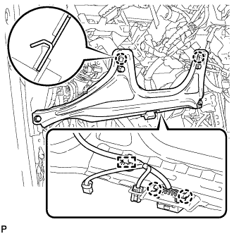 |
Connect the connector and engage the clamp.
Engage the 2 claws to install the safety pad insert.
Install the 4 <A> bolts.
| 5. INSTALL LOWER INSTRUMENT PANEL FINISH PANEL SUB-ASSEMBLY LH |
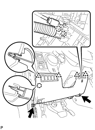 |
Engage the 2 claws and install the sensor.
Connect the connectors.
Engage the 4 clips and claw and install the finish panel.
Install the 2 <A> bolts.
| 6. INSTALL HOOD LOCK CONTROL LEVER SUB-ASSEMBLY |
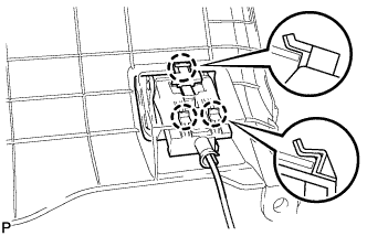 |
Connect the hood lock control cable assembly to the hood lock control lever sub-assembly.
engage the 3 claws to install the hood lock lever
| 7. INSTALL INSTRUMENT SIDE PANEL LH |
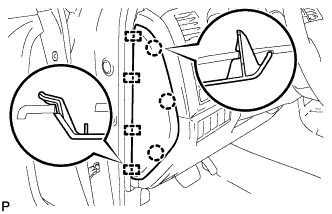 |
Engage the 4 guides and 3 claws and install the side panel.
| 8. INSTALL COWL SIDE TRIM BOARD LH |
| 9. INSTALL FRONT DOOR SCUFF PLATE LH |
| 10. CONNECT BRAKE BOOSTER CONNECTOR |
Connect the 2 brake booster connectors to the brake booster.
| 11. CONNECT VACUUM HOSE ASSEMBLY |
Connect the vacuum hose onto the check valve.
| 12. INSTALL BRAKE MASTER CYLINDER SUB-ASSEMBLY |
| 13. CHECK BRAKE PEDAL HEIGHT |
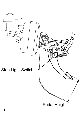 |
Check the brake pedal height.
| 14. CHECK BRAKE BOOSTER |
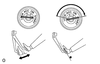 |
OPERATING CHECK
Depress the brake pedal several times with the engine off and check that there is no change in the pedal reserve distance.
Depress the brake pedal and start the engine. If the pedal goes down slightly, operation is normal.
 |
AIRTIGHTNESS CHECK
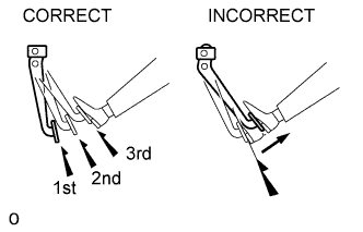
Start the engine and stop it after 1 or 2 minutes. Depress the brake pedal several times slowly.
If the pedal goes down farthest the 1st time, but gradually rises after the 2nd or 3rd time, the booster is airtight.
Depress the brake pedal while the engine is running, and stop the engine with the pedal depressed. If there is no change in the pedal reserve travel after holding the pedal for 30 seconds, the booster is airtight.
| 15. FILL RESERVOIR WITH BRAKE FLUID |
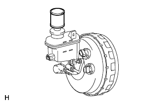 |
Set the brake fluid can upside down on the reservoir.
| 16. BLEED AIR FROM BRAKE MASTER CYLINDER |
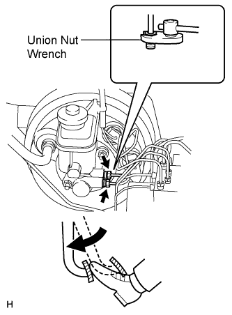 |
Using a union nut wrench, disconnect the 2 brake lines from the master cylinder.
Slowly depress and hold the brake pedal.
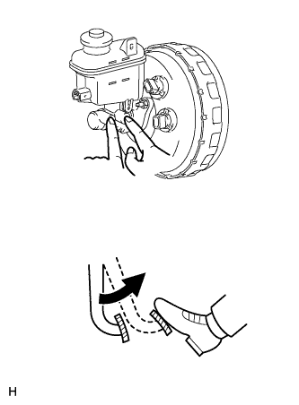 |
Block the outer holes with your fingers, and release the pedal.
Repeat the 2 previous steps 3 or 4 times.
Using a union nut wrench, connect the 2 brake lines to the master cylinder.
| 17. BLEED AIR FROM BRAKE LINE |
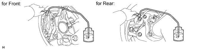
Remove the bleeder plug cap.
Connect the vinyl tube to the bleeder plug.
Depress the brake pedal several times, and then loosen the bleeder plug with the pedal depressed.
When fluid stops coming out, immediately tighten the bleeder plug. Then release the pedal.
Repeat the 2 previous steps until all the air in the brake fluid is gone.
Tighten the bleeder plug.
Install the cap.
Bleed air from the brake line for each wheel by repeating the above procedures.
| 18. BLEED AIR FROM VSC ACTUATOR ASSEMBLY |
Depress the brake pedal more than 20 times with the engine off.
Connect the Techstream to the DLC3, and turn the ignition switch ON.
Select AIR BLEEDING on the Techstream.
Bleed the air out of the suction line.
Connect a vinyl tube to the bleeder plug at the right front wheel or the right rear wheel.
Loosen the bleeder plug.
Operate the brake actuator to bleed the air using the Techstream.
Check if the operation has stopped by referring to the Techstream display.
Temporarily tighten the bleeder plug.
Repeat the 4 previous steps until all air in the fluid is completely bled out.
Tighten the bleeder plug.
Repeat all of the above procedures for the other wheel to bleed the air out of the suction line.
Bleed the air out of the pressure reduction line.
Connect a vinyl tube to one of the bleeder plugs.
Loosen the bleeder plug.
Using the Techstream, operate the brake actuator, completely depress the brake pedal and hold it there.
Tighten the bleeder plug, and then release the brake pedal.
Repeat the 3 previous steps until all air in the fluid is completely bled out.
Tighten the bleeder plug.
Repeat all of the above procedures for the other wheels to bleed the air out of the pressure reduction line.
| 19. CHECK BRAKE FLUID LEVEL IN RESERVOIR |
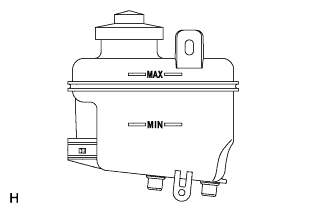 |
Check the fluid level and add fluid if necessary.
| 20. INSPECT FOR BRAKE FLUID LEAK |