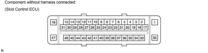
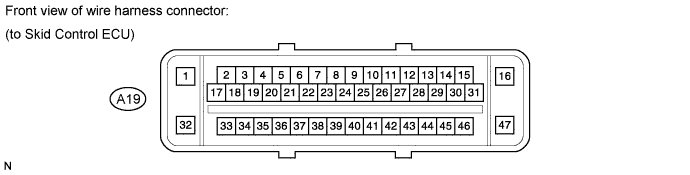
Terminal No. (Symbol)
| Wiring Color
| Terminal Description
| Condition
| Specified Condition
|
A19-1 (GND1) - Body ground
| W-B - Body ground
| Skid control ECU ground
| Always
| Below 1 Ω
|
A19-2 (STP0) - Body ground
| BR - Body ground
| Stop light control relay (BRK NO. 1) signal input
| Ignition switch ON
| 11 to 14 V
|
A19-3 (PKB2) - Body ground
| LG - Body ground
| Parking brake switch signal input
| Parking brake switch ON
| Below 1 Ω
|
A19-4 (CANL) - A19-5 (CANH)
| W - B
| CAN BUS
| Always
| 54 to 69 Ω
|
A19-5 (CANH) - A19-4 (CANL)
| B - W
| CAN BUS
| Always
| 54 to 69 Ω
|
A19-6 (EXI2) - Body ground
| GR - Body ground
| Center differential lock detection switch signal input (4WD)
| Center differential lock detection switch ON
| Below 1 Ω
|
A19-7 (D/G) - H19-7 (SIL)
| P - O
| Diagnosis tester communication line
| Always
| Below 1 Ω
|
A19-8 (BZ) - Body ground
| Y - Body ground
| Buzzer drive input
| Ignition switch ON
| 11 to 14 V
|
A19-9 (IG1) - Body ground
| V - Body ground
| IG1 power supply
| Ignition switch ON
| 11 to 14 V
|
A19-10 (TS) - H19-12 (TS)
| W - G
| Sensor check input
| Always
| Below 1 Ω
|
A19-11 (STP2) - Body ground
| GR - Body ground
| Stop light switch and stop light control relay (BRK NO. 1) signal input
| Brake pedal depressed
| 8 to 14 V
|
Brake pedal released
| Below 1.5 V
|
A19-13 (CSW) - Body ground
| P - Body ground
| VSC OFF switch signal input
| VSC OFF switch ON
| Below 1 Ω
|
A19-16 (+BM) - Body ground
| L - Body ground
| Motor relay power supply
| Always
| 11 to 14 V
|
A19-17 (BST) - A19-31 (BSTP)
| B - V
| Brake booster solenoid ground
| Always
| 1 to 2 Ω
|
A19-18 (PIM) - A19-21 (E3)
| R - BE
| Pedal stroke sensor (Delta S sensor) input line
| Always
| 4 to 8 kΩ
|
A19-19 (GYAW) - O12-5 (GYAW)*1
| P - G
| Yaw rate sensor ground
| Always
| Below 1 Ω
|
A19-19 (GYAW) - O11-5 (GYAW)*2
|
A19-21 (E3) - Body ground
| BE - Body ground
| Pedal stroke sensor (Delta S sensor) ground
| Always
| 10 kΩ or higher
|
A19-22 (VCP) - A19-21 (E3)
| G - BE
| Pedal stroke sensor (Delta S sensor) power source
| Always
| 150 to 200 Ω
|
A19-24 (PSNO) - A19-27 (STS)
| LG - SB
| Brake booster micro switch (Normal Open) signal input
| Brake pedal depressed
| Below 1 Ω
|
A19-25 (PSNC) - A19-27 (STS)
| L - SB
| Brake booster micro switch (Normal Close) signal input
| Always
| Below 1 Ω
|
A19-26 (VYS) - O12-3 (VYS)*1
| R - R
| Yaw rate sensor power source
| Always
| Below 1 Ω
|
A19-26 (VYS) - O11-3 (VYS)*2
|
A19-27 (STS) - A19-25 (PSNC)
| SB - L
| Brake booster micro switch power source
| Always
| Below 1 Ω
|
A19-29 (SS2) - O12-1 (YAW2)*1
| W - W
| Yaw rate sensor signal line (CANL)
| Always
| Below 1 Ω
|
A19-29 (SS2) - O11-1 (YAW2)*2
|
A19-30 (SS1) - O12-2 (YAW1)*1
| B - B
| Yaw rate sensor signal line (CANH)
| Always
| Below 1 Ω
|
A19-30 (SS1) - O11-2 (YAW1)*2
|
A19-31 (BSTP) - A19-17 (BST)
| V - B
| Brake booster solenoid power source
| Always
| 1 to 2 Ω
|
A19-33 (FL-) - z4-1
| LG - B
| Front wheel LH speed signal line
| Always
| Below 1 Ω
|
A19-34 (FL+) - z4-2
| V - W
| Front wheel LH speed signal line
| Always
| Below 1 Ω
|
A19-35 (BSW) - Body ground
| L - Body ground
| Stop light control relay (BRK NO. 2) drive input
| Ignition switch ON
| 11 to 14 V
|
A19-36 (RR+) - z5-2
| B - W
| Rear wheel RH speed signal line
| Always
| Below 1 Ω
|
A19-37 (RR-) - z5-1
| W - B
| Rear wheel RH speed signal line
| Always
| Below 1 Ω
|
A19-39 (PSOO) - A27-36 (STV)
| SB - SB
| Brake booster micro switch signal line
| Always
| Below 1 Ω
|
A19-41 (STP) - Body ground
| Y - Body ground
| Stop light switch signal input
| Brake pedal depressed
| 8 to 14 V
|
Brake pedal released
| Below 1.5 V
|
A19-42 (RL-) - z6-1
| P - B
| Rear wheel LH speed signal line
| Always
| Below 1 Ω
|
A19-43 (RL+) - z6-2
| L - W
| Rear wheel LH speed signal line
| Always
| Below 1 Ω
|
A19-45 (FR+) - z3-2
| BE - W
| Front wheel RH speed signal line
| Always
| Below 1 Ω
|
A19-46 (FR-) - z3-1
| G - B
| Front wheel RH speed signal line
| Always
| Below 1 Ω
|
A19-47 (+BS) - Body ground
| R - Body ground
| Solenoid relay power supply
| Always
| 11 to 14 V
|