LASER SENSOR > ADJUSTMENT |
| 1. ADJUST LASER SENSOR |
|
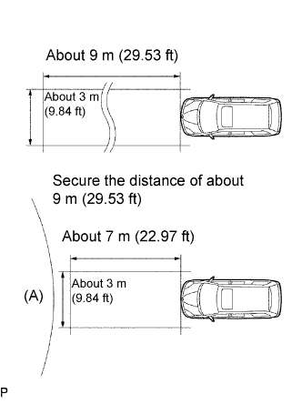
Preparation for adjusting the laser beam axis
Adjust the tires pressure properly (Click here).
Luggage in the vehicle, such as in the trunk, should be unloaded.
Clean the light-emitting and light-receiving portions of the laser sensor.
Prepare a 10 m (32.81 ft) string, a string with a sharp-pointed weight (plumb bob), and a 5 m (16.41 ft) tape measure.
Reflector (SST) placement
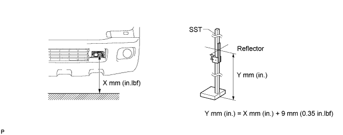
Measure the height to the center of the laser luminous portion.
Adjust the center height of the reflector 9 mm (0.35 in.) higher than the center of the luminous portion.
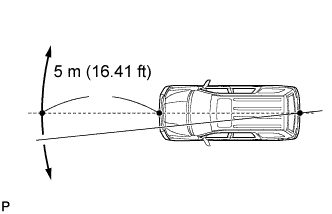 |
From the center (center of the emblem) of the front and rear bumpers, hang down the string with the plumb bob and mark the center points (both front and rear) of the vehicle on the ground.
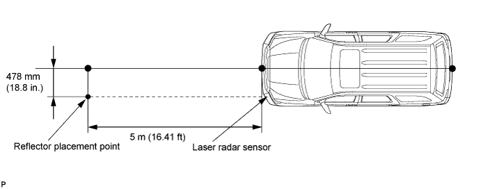
Make a 5 m (16.41 ft) mark when the string and the front vehicle center mark intersect.
From the 5 m (16.41 ft) marked position, measure 478 mm (18.8 in.) to the right and place the reflector there.
Adjustment of the laser beam axis
Connect the Techstream to the Data Link Connector 3 (DLC3).
Turn the ignition switch to ON.
Turn the Techstream main switch on, and turn the cruise control main switch on.
Enter the following menus: Powertrain / Laser Cruise / Utility / Beam Axis Adjustment.
Follow the Techstream display, and continue with the adjustment.
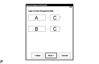 |
Confirm the current value of the laser beam (The default reading is 6.3° when the reflector position is out of range.)
Move the reflector either to the right or left by 100 mm (19.69 in.) and check that the value changes.
Return the reflector to the original position and read the current angle.
| Display | Angle |
| Upper/Lower Side | Below 2.7° |
| Right/Left Side | Below 4.0° |
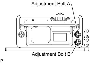 |
If the values are out of the auto axis adjustment range or the values are not displayed, it is not possible to operate Beam Axis Adjustment. In this case, mechanically adjust the direction of the radar sensor by adjustment bolts A and B to make the values within the standard value ranges.
Turn the headlight dimmer switch to the TAIL position.
Beam Axis Adjustment will be performed automatically.
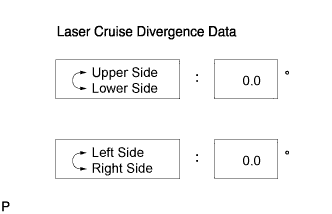 |
When the adjustment is completed, the Upper/Lower Side and Right/Left Side indicators show 0 and the system beeps for 10 seconds. During this time, Upper and Lower flash alternately on the screen, and Left and Right flash alternately on the screen.
|
Mechanical adjustment method.
Adjust the direction of the radar with adjustment bolts A and B until the values are within the auto axis adjustment range. Move the reflector from the default position as necessary (Upper/Lower, Right/Left) to find the reflector position where the current angle can be read using the Techstream. Adjust the direction of the reflector in the inverse of the direction moved by adjustment bolts A and B until the values are within the standard value ranges.
| Adjust Direction | Adjust Method | Adjust Angle |
| Upper | Rotate adjustment bolt B in (+) direction | 3/4 turn changes the angle 1° |
| Lower | Rotate adjustment bolt B in (-) direction | 3/4 turn changes the angle 1° |
| Left | Rotate adjustment bolts A and B in (-) direction | 4.5 turns changes the angle 1° |
| Right | Rotate adjustment bolts A and B in (+) direction | 4.5 turns changes the angle 1° |