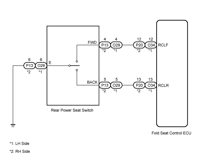
REAR POWER SEAT CONTROL SYSTEM > Rear Power Seat Switch Circuit |
| 1.CHECK FOLD SEAT CONTROL ECU (INPUT SIGNAL) |
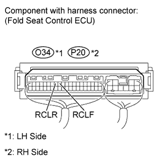 |
Measure the voltage according to the value(s) in the table below.
| Tester Connection | Condition | Specified Condition |
| O34-12 (RCLF) - Body ground | Always | 11 to 14 V |
| Rear power seat switch LH forward | Below 1 V | |
| O34-13 (RCLR) - Body ground | Always | 11 to 14 V |
| Rear power seat switch LH backward | Below 1 V |
| Tester Connection | Condition | Specified Condition |
| P20-12 (RCLF) - Body ground | Always | 11 to 14 V |
| Rear power seat switch RH forward | Below 1 V | |
| P20-13 (RCLR) - Body ground | Always | 11 to 14 V |
| Rear power seat switch RH backward | Below 1 V |
|
| ||||
| OK | ||
 | ||
| ||
| 2.INSPECT REAR POWER SEAT SWITCH |
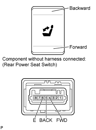 |
Remove the rear power seat switch (Click here).
Measure the resistance according to the value(s) in the table below.
| Tester Connection | Condition | Specified Condition |
| 4 (FWD) - 6 (E) | Always | 10 kΩ or higher |
| Rear power seat switch forward | Below 1 Ω | |
| 5 (BACK) - 6 (E) | Always | 10 kΩ or higher |
| Rear power seat switch backward | Below 1 Ω |
|
| ||||
| OK | |
 |
| 3.CHECK HARNESS AND CONNECTOR (FOLD SEAT CONTROL ECU - REAR POWER SEAT SWITCH) |
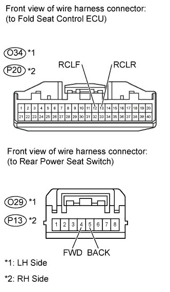 |
Disconnect the O34 or P20 ECU connector.
Disconnect the O29 or P13 switch connector.
Disconnect the connector from the folding motor.
Measure the resistance according to the value(s) in the table below.
| Tester Connection | Condition | Specified Condition |
| O34-12 (RCLF) - O29-4 (FWD) | Always | Below 1 Ω |
| O34-12 (RCLF) - Body ground | Always | 10 kΩ or higher |
| O34-13 (RCLR) - O29-5 (BACK) | Always | Below 1 Ω |
| O34-13 (RCLR) - Body ground | Always | 10 kΩ or higher |
| Tester Connection | Condition | Specified Condition |
| P20-12 (RCLF) - P13-4 (FWD) | Always | Below 1 Ω |
| P20-12 (RCLF) - Body ground | Always | 10 kΩ or higher |
| P20-13 (RCLR) - P13-5 (BACK) | Always | Below 1 Ω |
| P20-13 (RCLR) - Body ground | Always | 10 kΩ or higher |
|
| ||||
| OK | ||
| ||
| ||

