 |
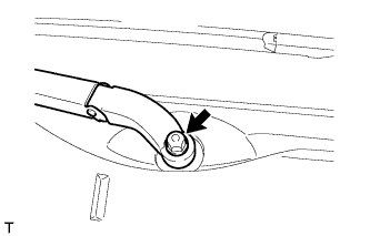
Remove the nut and remove the wiper arm and blade assembly.
AIR PUMP > REMOVAL |
| 1. DISCHARGE FUEL SYSTEM PRESSURE |
| 2. REMOVE FRONT WIPER ARM AND BLADE ASSEMBLY RH |
|
Remove the nut and remove the wiper arm and blade assembly.
| 3. REMOVE FRONT WIPER ARM AND BLADE ASSEMBLY LH |
| 4. REMOVE FRONT FENDER TO COWL SIDE SEAL RH |
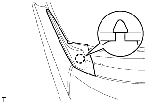 |
Disengage the claw and remove the front fender to cowl side seal.
| 5. REMOVE FRONT FENDER TO COWL SIDE SEAL LH |
| 6. REMOVE COWL TOP VENTILATOR LOUVER SUB-ASSEMBLY |
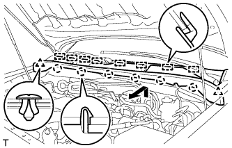 |
Remove the 2 clips.
Remove the 6 claws and 8 guides and remove the cowl top ventilator louver sub-assembly.
| 7. REMOVE FRONT WIPER MOTOR AND LINK ASSEMBLY |
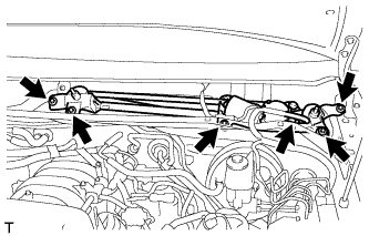 |
Disconnect the connector.
Remove the nut.
Remove the 4 bolts and wiper motor and link assembly.
| 8. REMOVE FRONT COWL TOP OUTER PANEL SUB-ASSEMBLY |
Disconnect the washer hose.
Separate the washer hose grommet from the front cowl top outer panel sub-assembly.
Separate the wire harness clamp from the front cowl top outer panel sub-assembly.
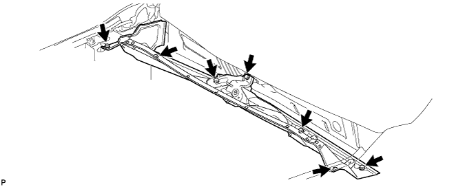
Remove the 7 bolts and front cowl top outer panel sub-assembly.
| 9. REMOVE NO. 1 ENGINE UNDER COVER |
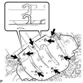 |
Remove the 3 screws and 5 bolts.
Unhook the engine under cover from the vehicle body as shown in the illustration.
| 10. DRAIN ENGINE COOLANT |
Loosen the radiator drain cock plug and 2 cylinder block drain cock plugs.
Remove the radiator cap. Then drain the coolant.
Tighten the 2 cylinder block drain cock plugs.
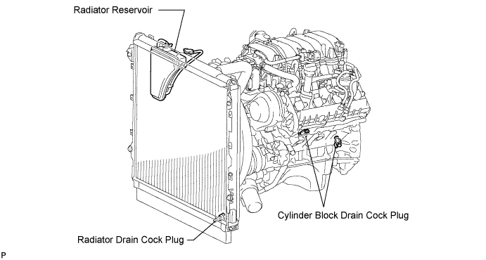
Tighten the radiator drain cock plug by hand.
| 11. REMOVE THROTTLE BODY COVER SUB-ASSEMBLY |
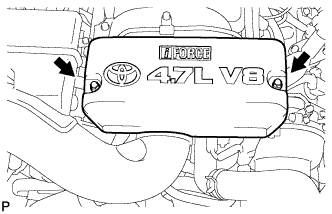 |
Remove the 2 nuts and throttle body cover sub-assembly.
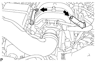 |
Remove the 2 bolts and 2 throttle body cover brackets from the intake manifold.
| 12. REMOVE AIR CLEANER HOSE ASSEMBLY |
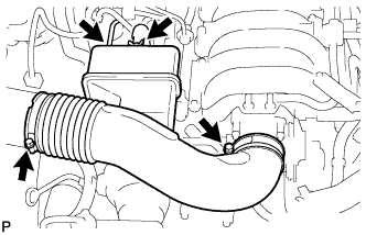 |
Disconnect the vacuum hose and No. 2 ventilation hose.
Loosen the 2 hose clamps and remove the air cleaner hose assembly.
| 13. REMOVE VACUUM HOSE ASSEMBLY |
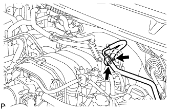 |
Remove the bolt and disconnect the vacuum hose assembly.
| 14. REMOVE NO. 2 WATER BY-PASS PIPE |
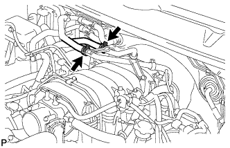 |
Disconnect the 2 water hoses from the No. 2 water by-pass pipe.
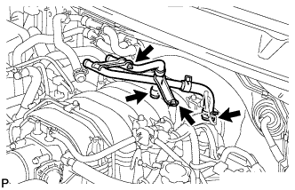 |
Remove the 2 bolts.
Disconnect the 2 water hoses and remove the No. 2 water by-pass pipe.
| 15. DISCONNECT FUEL RETURN TUBE |
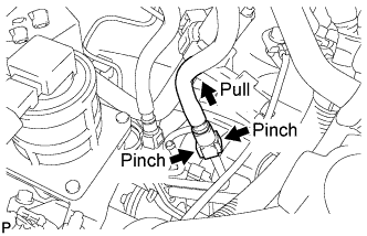 |
Disconnect the No. 1 fuel pipe sub-assembly (Click here).
| 16. DISCONNECT FUEL MAIN TUBE |
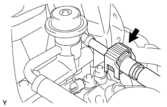 |
Disconnect the No. 2 fuel pipe sub-assembly (Click here).
| 17. REMOVE INTAKE MANIFOLD |
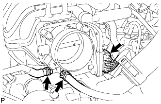 |
Disconnect the throttle body connector.
Disconnect the 2 water by-pass hoses from the throttle body assembly.
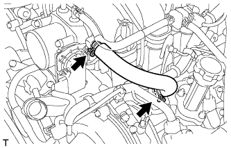 |
Loose the 2 clamps and remove the No. 1 ventilation hose.
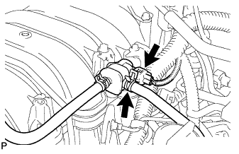 |
Disconnect the purge VSV connector.
Disconnect the purge line hose from the purge VSV.
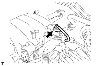 |
Disconnect the vacuum switching valve assembly (for ACIS) connector.
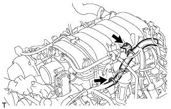 |
Disconnect the wire harness clamp from the engine hanger.
Remove the bolt and wire harness bracket from the intake manifold assembly.
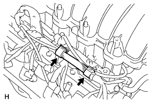 |
Disconnect the 2 wire clamps.
Disconnect the 8 injector connectors.
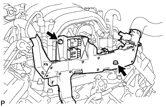 |
Remove the 2 bolts and separate the engine wire protector.
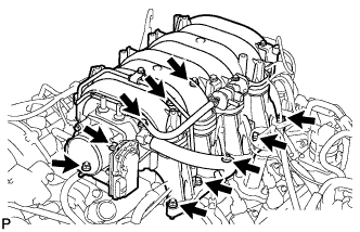 |
Remove the 6 bolts, 4 nuts, intake manifold assembly and 2 gaskets.
| 18. REMOVE WATER BY-PASS PIPE SUB-ASSEMBLY |
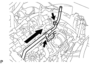 |
Disconnect the connector clamp.
Remove the bolt.
Pull out the water by-pass pipe sub-assembly.
Remove the O-ring from the water by-pass pipe sub-assembly.
| 19. REMOVE NO. 1 AIR INJECTION SYSTEM HOSE |
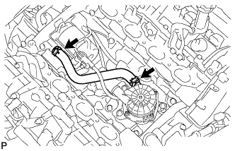 |
Loosen the 2 clips and remove the No. 1 air injection system hose.
| 20. REMOVE AIR PUMP ASSEMBLY (for Bank 1) |
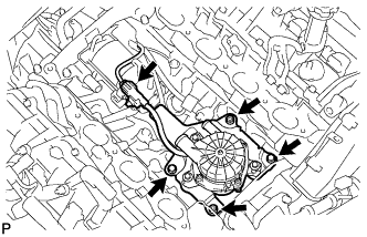 |
Disconnect the air pump assembly connector.
Remove the 2 bolts, 2 nuts and air pump assembly.
| 21. REMOVE AIR PUMP BRACKET |
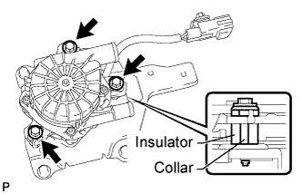 |
Remove the 3 bolts, 3 collars, 3 insulators and air pump bracket.
| 22. REMOVE FRONT FENDER LINER RH |
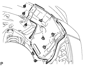 |
Remove the 9 clips and front fender liner RH.
| 23. REMOVE NO. 2 AIR INJECTION SYSTEM HOSE |
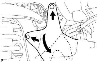 |
Using a clip remover, remove the 2 clips.
Fold back the fender apron seal.
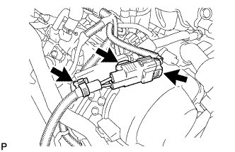 |
Disconnect the air pump assembly connector.
Disconnect the 2 clamps.
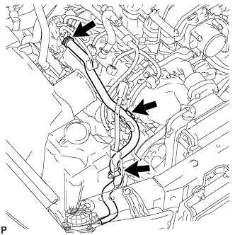 |
Remove the air injection system hose.
| 24. REMOVE AIR PUMP ASSEMBLY (for Bank 2) |
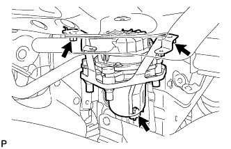 |
Remove the bolt, 2 nuts and air pump assembly.
| 25. REMOVE AIR PUMP INLET |
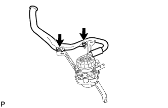 |
Remove the 2 bolts and air pump inlet.
| 26. REMOVE NO. 1 AIR INJECTION SYSTEM HOSE |
| 27. REMOVE NO. 1 AIR PUMP BRACKET |
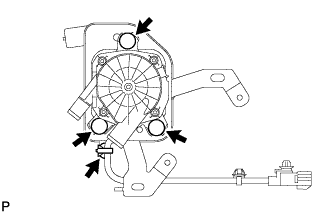 |
Disconnect the clamp.
Remove the 3 air pump insulators and remove the air pump assembly from the No. 1 air pump bracket.