 |
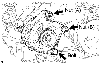
Install the generator assembly with the bolt and 2 nuts.
- for bolt and nut (A)
- Torque:
- 39 N*m{ 398 kgf*cm , 29 ft.*lbf }
- for nut (B)
- Torque:
- 16 N*m{ 163 kgf*cm , 12 ft.*lbf }
GENERATOR > INSTALLATION |
| 1. INSTALL GENERATOR ASSEMBLY |
|
Install the generator assembly with the bolt and 2 nuts.
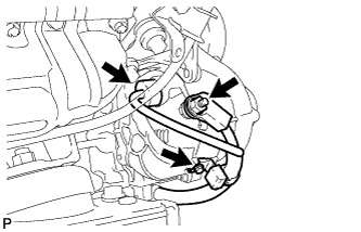 |
Connect the generator connector.
Connect the generator wire with the nut.
Install the terminal cap.
Install the harness bracket to the generator assembly with the bolt.
| 2. INSTALL VANE PUMP ASSEMBLY |
Install the vane pump assembly with 2 bolts.
Connect the connector.
| 3. INSTALL FAN AND GENERATOR V BELT |
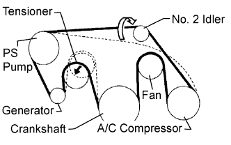 |
Set the V belt onto every part except the No. 2 idler pulley, as shown in the illustration.
Loosen the V belt by turning the belt tensioner counterclockwise.
Set the V belt to the No. 2 idler pulley.
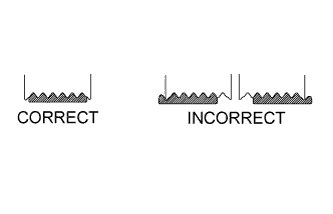 |
After installing the belt, check that it fits properly in the ribbed grooves.
Check by hand to confirm that the belt has not slipped out of the grooves on the bottom of the pulley.
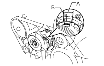 |
Check that the arrow on the belt tensioner is within area "A".
If it is outside area "A", replace the fan and generator V belt.
| 4. INSTALL AIR CLEANER HOSE ASSEMBLY |
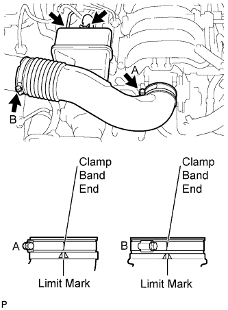 |
Install the air cleaner hose assembly with the 2 clamps.
Connect the vacuum hose and No. 2 ventilation hose.
| 5. INSTALL THROTTLE BODY COVER SUB-ASSEMBLY |
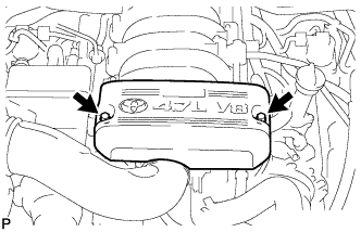 |
Install the throttle body cover sub-assembly with the 2 nuts.
| 6. INSTALL NO. 1 ENGINE UNDER COVER SUB-ASSEMBLY |
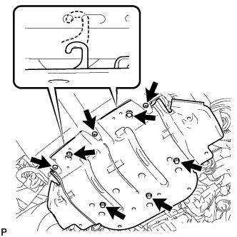 |
Hook the engine under cover onto the vehicle body as shown in the illustration.
Install the 3 screws and 5 bolts.
| 7. CONNECT CABLE TO NEGATIVE BATTERY TERMINAL |