Home › Engine / Hybrid System ยท 3UR-FBE › INTAKE / EXHAUST › EXHAUST PIPE

EXHAUST PIPE > INSTALLATION

for Preparation Click here


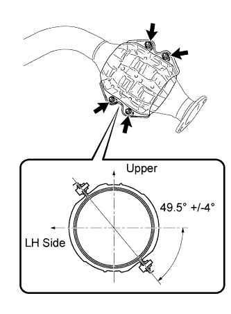
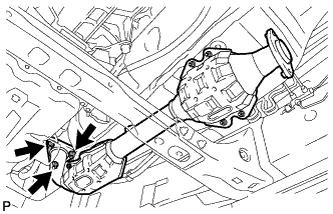
1. INSTALL MONOLITHIC CONVERTER PROTECTOR (for Bank 1)


A184935E02
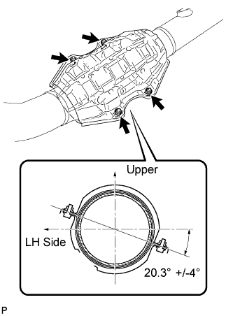
  1. Install the 2 LH converter protector stays and 2 No. 2 converter protector stays.

  1. Install the 2 monolithic converter protectors with the 4 bolts and 4 nuts.

    Torque:
    11 N*m{ 107 kgf*cm , 8 ft.*lbf }

    HINT:
    Install the monolithic converter protector within the angle range shown in the illustration.


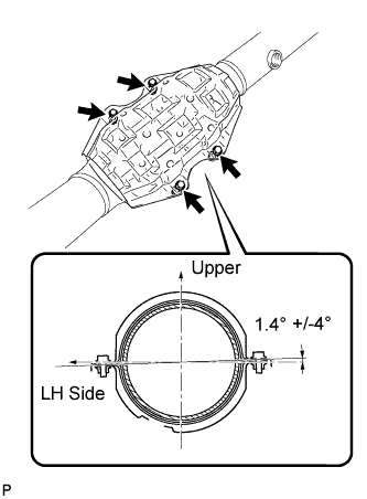
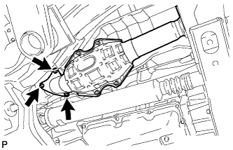
2. INSTALL NO. 1 MONOLITHIC CONVERTER PROTECTOR (for Bank 1)


A184937E02
  1. Install the 2 No. 2 converter protector stays and 2 No. 3 converter protector stays.

  1. Install the 2 No. 1 monolithic converter protectors with 4 the bolts and 4 nuts.

    Torque:
    11 N*m{ 107 kgf*cm , 8 ft.*lbf }

    HINT:
    Install the monolithic converter protector within the angle range shown in the illustration.


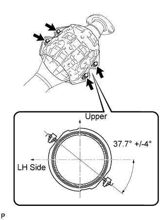
3. INSTALL MONOLITHIC CONVERTER PROTECTOR (for Bank 2)


A184931E02
  1. Install the 2 LH converter protector stays and 2 No. 2 converter protector stays.

  1. Install the 2 monolithic converter protectors with 4 bolts and 4 nuts.
    Install the 2 No. 1 monolithic converter protectors with the 4 bolts and 4 nuts.

    Torque:
    11 N*m{ 107 kgf*cm , 8 ft.*lbf }

    HINT:
    Install the monolithic converter protector within the angle range shown in the illustration.


4. INSTALL NO. 1 MONOLITHIC CONVERTER PROTECTOR (for Bank 2)


A184933E02
  1. Install the 2 No. 2 converter protector stays and 2 No. 3 converter protector stays.

  1. Install the 2 No. 1 monolithic converter protectors with 4 bolts and 4 nuts.

    Torque:
    11 N*m{ 107 kgf*cm , 8 ft.*lbf }

    HINT:
    Install the monolithic converter protector within the angle range shown in the illustration.


5. INSTALL AIR FUEL RATIO SENSOR (for Bank 1 Sensor 1)


    A194685
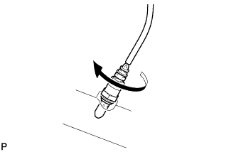
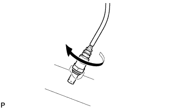
  1. Install the air fuel ratio sensor to the front exhaust pipe assembly by hand.


    A194686E01
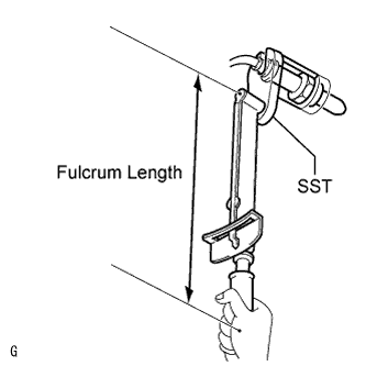
  1. Using SST, tighten the air fuel ratio sensor.

    SST
    09224-00010  

    Torque:
    without SST:
    44 N*m{ 449 kgf*cm , 32 ft.*lbf }
    with SST:
    40 N*m{ 408 kgf*cm , 30 ft.*lbf }

    HINT:
    1. Use a torque wrench with a fulcrum length of 30 cm (11.8 in.). If using a torque wrench with a length that is not 30 cm (11.8 in.), calculate the torque specification for the torque wrench and SST based on the "without SST" torque specification (Click here).
    2. Make sure SST and the wrench are connected in a straight line.


6. INSTALL AIR FUEL RATIO SENSOR (for Bank 2 Sensor 1)


    A194685
  1. Install the air fuel ratio sensor to the front No. 2 exhaust pipe assembly by hand.


    A194686E01
  1. Using SST, tighten the air fuel ratio sensor.

    SST
    09224-00010  

    Torque:
    without SST:
    44 N*m{ 449 kgf*cm , 32 ft.*lbf }
    with SST:
    40 N*m{ 408 kgf*cm , 30 ft.*lbf }

    HINT:
    1. Use a torque wrench with a fulcrum length of 30 cm (11.8 in.). If using a torque wrench with a length that is not 30 cm (11.8 in.), calculate the torque specification for the torque wrench and SST based on the "without SST" torque specification (Click here).
    2. Make sure SST and the wrench are connected in a straight line.


7. INSTALL FRONT EXHAUST PIPE ASSEMBLY


A184929
  1. Install a new gasket and the front exhaust pipe to the exhaust manifold RH with 3 new nuts.

    Torque:
    54 N*m{ 554 kgf*cm , 40 ft.*lbf }

  1. Connect the air fuel ratio sensor connector.


8. INSTALL FRONT NO. 2 EXHAUST PIPE ASSEMBLY


A184928
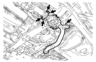
  1. Install a new gasket and the front No. 2 exhaust pipe to the exhaust manifold LH with 3 new nuts.

    Torque:
    54 N*m{ 554 kgf*cm , 40 ft.*lbf }

  1. Connect the air fuel ratio sensor connector.


    A184927
  1. Connect the front No. 3 exhaust pipe to the exhaust pipe support.

  1. Install a new gasket and the front No. 3 exhaust pipe sub-assembly to the No. 2 exhaust pipe sub-assembly with the 2 bolts and 2 new nuts.

    Torque:
    48 N*m{ 489 kgf*cm , 35 ft.*lbf }


9. INSTALL HEATED OXYGEN SENSOR (for Bank 1 Sensor 2)


    A158663
  1. Install the heated oxygen sensor to the front exhaust pipe assembly by hand.


    A184942E02
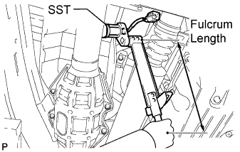
  1. Using SST, tighten the heated oxygen sensor.

    SST
    09224-00010  

    Torque:
    without SST:
    44 N*m{ 449 kgf*cm , 32 ft.*lbf }
    with SST:
    40 N*m{ 408 kgf*cm , 30 ft.*lbf }

    HINT:
    1. Use a torque wrench with a fulcrum length of 30 cm (11.8 in.). If using a torque wrench with a length that is not 30 cm (11.8 in.), calculate the torque specification for the torque wrench and SST based on the "without SST" torque specification (Click here).
    2. Make sure SST and the wrench are connected in a straight line.

  1. Connect the heated oxygen sensor connector.


10. INSTALL HEATED OXYGEN SENSOR (for Bank 2 Sensor 2)


    A158663
  1. Install the heated oxygen sensor to the front No. 2 exhaust pipe assembly by hand.
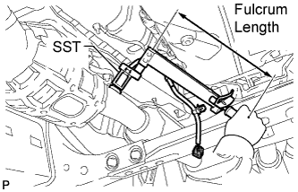


    A184940E02
  1. Using SST, tighten the heated oxygen sensor.

    SST
    09224-00010  

    Torque:
    without SST:
    44 N*m{ 449 kgf*cm , 32 ft.*lbf }
    with SST:
    40 N*m{ 408 kgf*cm , 30 ft.*lbf }

    HINT:
    1. Use a torque wrench with a fulcrum length of 30 cm (11.8 in.). If using a torque wrench with a length that is not 30 cm (11.8 in.), calculate the torque specification for the torque wrench and SST based on the "without SST" torque specification (Click here).
    2. Make sure SST and the wrench are connected in a straight line.

  1. Connect the heated oxygen sensor connector and 2 clamps.


11. INSTALL CENTER EXHAUST PIPE ASSEMBLY


A184926
  1. Connect the center exhaust pipe to the 3 exhaust pipe supports.

  1. Install 2 new gaskets to the front exhaust pipe.

  1. Install the center exhaust pipe with the 4 bolts.

    Torque:
    48 N*m{ 489 kgf*cm , 35 ft.*lbf }


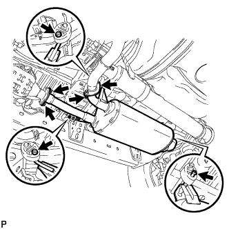
12. INSTALL TAILPIPE ASSEMBLY
  1. Connect the tailpipe to the exhaust pipe support.


    A184938E01
  1. Install a new gasket to the center exhaust pipe.

  1. Connect the tailpipe to the center exhaust pipe.

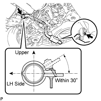
  1. Attach a new clamp to the tailpipe and center exhaust pipe. Then install the bolt to the clamp.

    Torque:
    32 N*m{ 326 kgf*cm , 24 ft.*lbf }

    HINT:
    Install the clamp within the angle range shown in the illustration.


13. INSPECT FOR EXHAUST GAS LEAK
If gas is leaking, tighten the areas necessary to stop the leak. Replace damaged parts as necessary.