 |
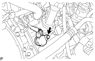
Install the 8 ignition coil assemblies with the 8 bolts.
- Torque:
- 7.5 N*m{ 76 kgf*cm , 66 in.*lbf }
IGNITION COIL AND SPARK PLUG > INSTALLATION |
| 1. INSTALL SPARK PLUG |
Using a 16 mm plug wrench, install the 8 spark plugs.
| 2. INSTALL IGNITION COIL ASSEMBLY |
|
Install the 8 ignition coil assemblies with the 8 bolts.
Connect the 8 ignition coil assembly connectors.
| 3. INSTALL AIR SWITCHING VALVE ASSEMBLY (for Bank 2) |
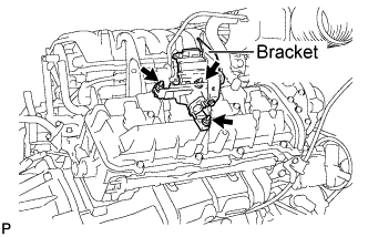 |
Install the air switching valve assembly with the 3 nuts.
| 4. INSTALL NO. 2 AIR TUBE |
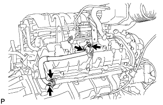 |
Temporarily install a new gasket and the No. 2 air tube to the exhaust manifold side with the 2 nuts.
Install a new gasket and the No. 2 air tube to the air switching valve side with the 2 nuts.
Tighten the 2 nuts on the exhaust manifold side.
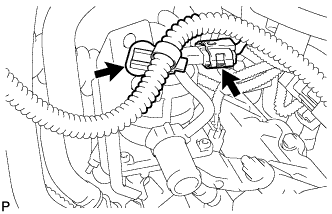 |
Connect the air switching valve assembly connector.
Connect the wire harness clamp.
| 5. CONNECT NO. 2 AIR INJECTION SYSTEM HOSE |
Connect the No. 2 air injection system hose to the air switching valve assembly.
| 6. CONNECT NO. 1 WATER BY-PASS PIPE |
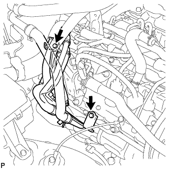 |
Connect the No. 1 water by-pass pipe with the 2 bolts.
| 7. INSTALL FRONT FENDER APRON SEAL RH |
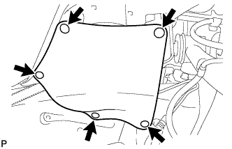 |
Install the front fender apron seal RH with the 5 clips.
| 8. INSTALL AIR SWITCHING VALVE ASSEMBLY (for Bank 1) |
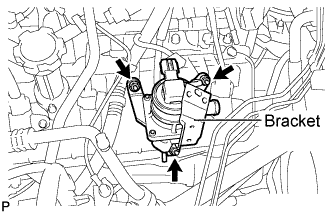 |
Install the air switching valve assembly with the 3 nuts.
| 9. INSTALL NO. 3 AIR TUBE |
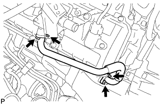 |
Temporarily install a new gasket and the No. 3 air tube to the exhaust manifold side with the 2 nuts.
Install a new gasket and the No. 3 air tube to the air switching valve side with the 2 nuts.
Tighten the 2 nuts on the exhaust manifold side.
| 10. INSTALL NO. 2 AIR HOSE |
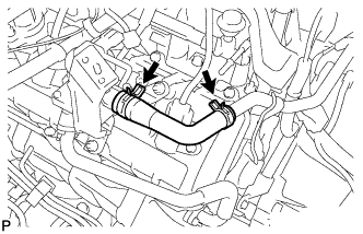 |
Install the No. 2 air hose.
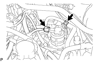 |
Connect the air switching valve assembly connector.
Connect the fuel hose clamp.
| 11. INSTALL FRONT FENDER APRON SEAL LH |
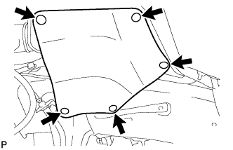 |
Install the front fender apron seal LH with the 5 clips.
| 12. INSTALL AIR CLEANER HOSE ASSEMBLY |
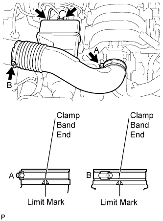 |
Install the air cleaner hose assembly with the 2 clamps.
Connect the vacuum hose and No. 2 ventilation hose.
| 13. INSTALL THROTTLE BODY COVER ASSEMBLY |
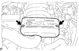 |
Install the throttle body cover sub-assembly with the 2 nuts.