 |
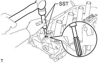
Using SST and a hammer, tap out the valve guide bush.
- SST
- 09201-10000
(09201-01050)
09950-70010 (09951-07100)
CYLINDER HEAD > REPLACEMENT |
| 1. REPLACE INTAKE VALVE GUIDE BUSH |
Heat the cylinder head to approximately 80 to 100°C (176 to 212°F).
Place the cylinder head on wooden blocks.
|
Using SST and a hammer, tap out the valve guide bush.
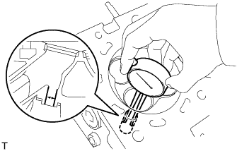 |
Using a caliper gauge, measure the bush bore diameter of the cylinder head side.
Select a new guide bush (STD or O/S 0.05), and measure its diameter.
Machine the bush bore diameter of the cylinder head side to the diameter of the selected guide bush.
| Bush Size | Specified Condition |
| STD | 10.333 to 10.344 mm (0.4068 to 0.4072 in.) |
| O/S 0.05 | 10.383 to 10.394 mm (0.4088 to 0.4092 in.) |
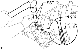 |
Using SST and a hammer, tap in a new guide bush to the standard protrusion height.
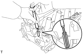 |
Using a sharp 5.5 mm reamer, ream the guide bush to obtain the standard oil clearance between the guide bush and valve stem.
| 2. REPLACE EXHAUST VALVE GUIDE BUSH |
Heat the cylinder head to approximately 80 to 100°C (176 to 212°F).
Place the cylinder head on wooden blocks.
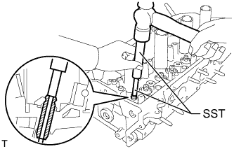 |
Using SST and a hammer, tap out the valve guide bush.
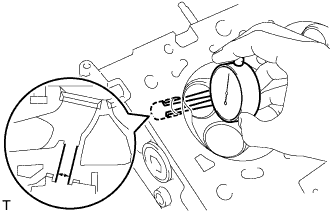 |
Using a caliper gauge, measure the bush bore diameter of the cylinder head.
Select a new guide bush (STD or O/S 0.05), and measure its diameter.
Machine the bush bore diameter of the cylinder head side to the diameter of the selected guide bush.
| Bush Size | Specified Condition |
| STD | 10.333 to 10.344 mm (0.4068 to 0.4072 in.) |
| O/S 0.05 | 10.383 to 10.394 mm (0.4088 to 0.4092 in.) |
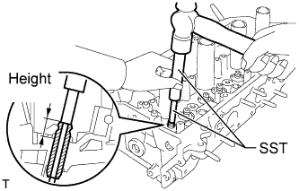 |
Using SST and a hammer, tap in a new guide bush to the standard protrusion height.
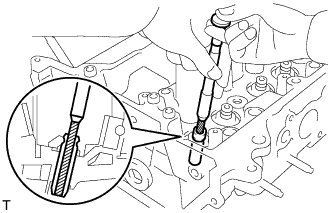 |
Using a sharp 5.5 mm reamer, ream the guide bush to obtain the standard oil clearance between the guide bush and valve stem.
| 3. REPLACE RING PIN |
Remove the ring pins.
Using a plastic-faced hammer, tap in new ring pins to the cylinder head.
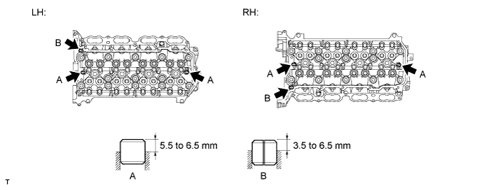
| Item | Specified Condition |
| Ring pin A | 5.5 to 6.5 mm (0.217 to 0.256 in.) |
| Ring pin B | 3.5 to 6.5 mm (0.138 to 0.256 in.) |