CENTER AIRBAG SENSOR ASSEMBLY > INSTALLATION |
| 1. INSTALL AIRBAG SENSOR ASSEMBLY |
|
Confirm that the ignition switch is turned off.
Confirm that the negative battery terminal is disconnected.
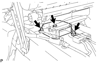
Install the airbag sensor with the 3 bolts.
Confirm that there is no looseness by shaking the front airbag sensor.
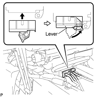 |
Connect the connector holder to lock the lever.
Confirm that the drip-proof sheet has not been removed and does not cut into the connectors.
| 2. INSTALL FRONT CONSOLE BOX |
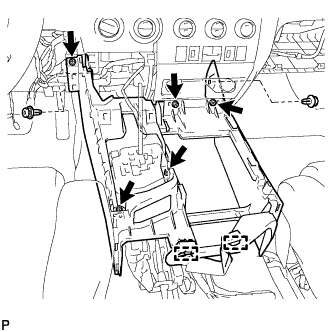 |
Install the front console box with the 5 screws and 2 clips.
Engage the 2 clamps.
| 3. INSTALL REAR CONSOLE BOX ASSEMBLY |
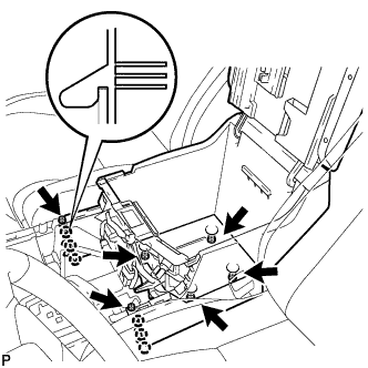 |
Engage the 6 claws and install the rear console box.
Install the 2 screws and 4 bolts.
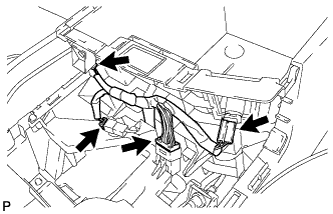 |
Connect the connectors.
| 4. INSTALL CONSOLE BOX CARPET |
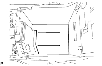 |
Install the console box carpet.
| 5. INSTALL REAR CONSOLE BOX POCKET |
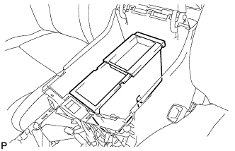 |
Install the rear console box pocket.
| 6. INSTALL REAR UPPER CONSOLE PANEL SUB-ASSEMBLY |
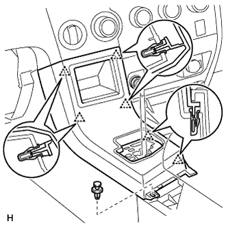 |
Connect the connectors.
Engage the 6 clips and install the console panel.
Install the clip.
| 7. INSTALL UPPER CONSOLE PANEL SUB-ASSEMBLY |
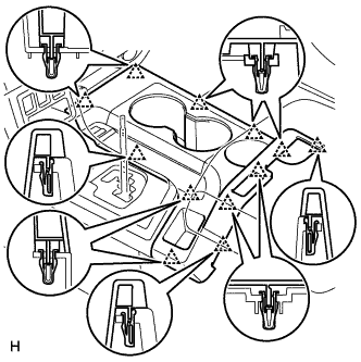 |
Engage the 12 clips and install the console panel.
| 8. INSTALL SHIFT LEVER KNOB SUB-ASSEMBLY |
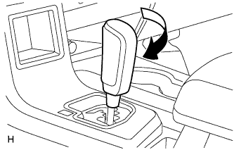 |
Install the shift lever knob and twist it in the direction indicated by the arrow.
| 9. INSTALL LOWER INSTRUMENT PANEL FINISH PANEL SUB-ASSEMBLY LH |
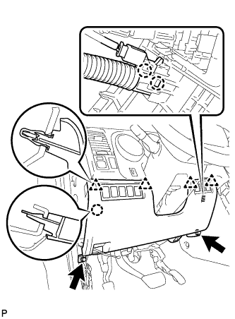 |
Engage the 2 claws and install the sensor.
Connect the connectors.
Engage the 4 clips and claw and install the finish panel.
Install the 2 <A> bolts.
| 10. INSTALL HOOD LOCK CONTROL LEVER SUB-ASSEMBLY |
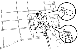 |
Connect the hood lock control cable assembly to the hood lock control lever sub-assembly.
engage the 3 claws to install the hood lock lever
| 11. INSTALL INSTRUMENT SIDE PANEL LH |
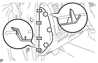 |
Engage the 4 guides and 3 claws and install the side panel.
| 12. INSTALL FRONT DOOR OPENING TRIM WEATHERSTRIP LH |
Install the front door opening trim weatherstrip LH.
| 13. INSTALL FRONT PILLAR GARNISH LH |
| 14. INSTALL COWL SIDE TRIM BOARD LH |
| 15. INSTALL FRONT DOOR SCUFF PLATE LH |
| 16. CONNECT CABLE TO NEGATIVE BATTERY TERMINAL |
| 17. INSPECT SRS WARNING LIGHT |
Inspect the SRS warning light (Click here).