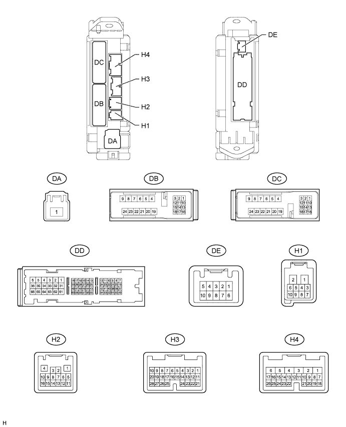
POWER DOOR LOCK CONTROL SYSTEM > TERMINALS OF ECU |
| CHECK MAIN BODY ECU (COWL SIDE JUNCTION BLOCK LH) |
Disconnect the H3, H4, DA, DB, DC and DD ECU connectors.
Measure the voltage and resistance according to the value(s) in the table below.
| Terminal No. (Symbol) | Wiring Color | Terminal Description | Condition | Specified Condition |
| DB-13 (BECU) - Body ground | GR - Body ground | +B power source | Always | 11 to 14 V |
| DA-1 (ALTB) - Body ground | B - Body ground | +B power source | Always | 11 to 14 V |
| DD-62 (GND1,GND2) - Body ground | W-B - Body ground | Power ground | Always | Below 1 Ω |
| H4-24 (DCTY) - Body ground | BR - Body ground | Driver door courtesy switch | Driver door CLOSED → OPEN | 10 kΩ or higher → Below 1 Ω |
| H3-21 (PCTY) - Body ground | O - Body ground | Front passenger door courtesy switch input | Front passenger door CLOSED → OPEN | 10 kΩ or higher → Below 1 Ω |
| DC-2 (LCTY) - Body ground | G - Body ground*1 B - Body ground*2 | Rear left door courtesy switch input | Rear left door CLOSED → OPEN | 10 kΩ or higher → Below 1 Ω |
| H3-25 (RRCY) - Body ground | L - Body ground | Rear right door courtesy switch input | Rear right door CLOSED → OPEN | 10 kΩ or higher → Below 1 Ω |
| DD-49 (L1) - Body ground | R - Body ground | Door control switch LOCK input | Front door control switch RH OFF → LOCK | 10 kΩ or higher → Below 1 Ω |
| DD-40 (UL1) - Body ground | W - Body ground | Front door control switch RH UNLOCK input | Front door control switch RH OFF → UNLOCK | 10 kΩ or higher → Below 1 Ω |
Reconnect the H3, H4, DA, DB, DC and DD ECU connectors.
Measure the voltage according to the value(s) in the table below.
| Terminal No. (Symbol) | Wiring Color | Terminal Description | Condition | Specified Condition |
| H4-9 (LSWD) - Body ground | P - Body ground | Front door unlock detection switch LH input | Front door LH UNLOCK | Below 1 V |
| Front door LH LOCK | 11 to 14 V (or pulse generation ) | |||
| H3-27 (LSWP) - Body ground | V - Body ground | Front door unlock detection switch RH input | Front door RH UNLOCK | Below 1 V |
| Front door RH LOCK | 11 to 14 V (or pulse generation ) | |||
| DC-1 (LSWL) - Body ground | GR - Body ground | Rear door unlock detection switch LH input | Rear door LH UNLOCK | Below 1 V |
| Rear door LH LOCK | 11 to 14 V (or pulse generation ) | |||
| H3-5 (LSWR) - Body ground | Y - Body ground | Rear door unlock detection switch RH input | Rear door RH UNLOCK | Below 1 V |
| Rear door RH LOCK | 11 to 14 V (or pulse generation ) | |||
| DD-3 (ACT+) - Body ground | W - Body ground | Door lock motor LOCK drive output | Door control switch or front door key cylinder LH OFF | Below 1 V |
| Door control switch or front door key cylinder LH LOCK | 11 to 14 V | |||
| H4-5 (ACTD) - Body ground | P - Body ground | Door lock motor UNLOCK drive output | Door control switch or front door key cylinder LH UNLOCK | 11 to 14 V |
| Door control switch or front door key cylinder LH OFF | Below 1 V | |||
| DD-2 (ACT-) - Body ground | L - Body ground | Door lock motor UNLOCK drive output | Door control switch or front door key cylinder LH UNLOCK | 11 to 14 V |
| Door control switch or front door key cylinder LH OFF | Below 1 V | |||
| DC-24 (ACT+) - Body ground | W - Body ground | Door lock motor LOCK drive output | Door control switch or front door key cylinder LH OFF | Below 1 V |
| Door control switch or front door key cylinder LH LOCK | 11 to 14 V | |||
| DC-23 (ACT-) - Body ground | L - Body ground | Door lock motor UNLOCK drive output | Door control switch or front door key cylinder LH UNLOCK | 11 to 14 V |
| Door control switch or front door key cylinder LH OFF | Below 1 V | |||
| DD-53 (L2) - Body ground | V - Body ground | Front door key switch LH LOCK input | Front door key cylinder LH LOCK | Below 1 V |
| Ignition switch off, all doors closed and front door key cylinder LH neutral position | 11 to 14 V (or pulse generation ) | |||
| H4-10 (UL3) - Body ground | B - Body ground | Front door key switch LH UNLOCK input | Front door key cylinder LH UNLOCK | Below 1 V |
| Ignition switch off, all doors closed and front door key cylinder LH neutral position | 11 to 14 V (or pulse generation ) |
| CHECK BACK DOOR ECU |
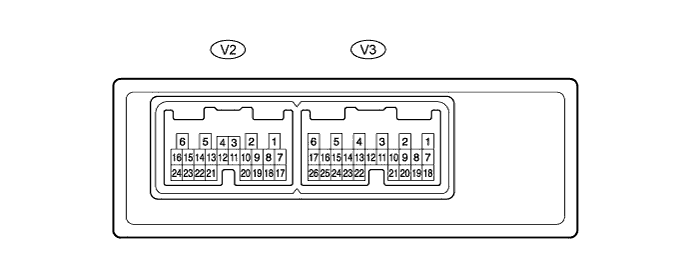
Disconnect the V2 and V3 ECU connectors.
Measure the voltage and resistance according to the value(s) in the table below.
| Terminal No. (Symbol) | Wiring Color | Terminal Description | Condition | Specified Condition |
| V2-1 (BDR) - Body ground | SB - Body ground | +B power source | Always | 11 to 14 V |
| V2-7 (BECU) - Body ground | GR - Body ground | +B power source | Always | 11 to 14 V |
| V2-6 (GND) - Body ground | W-B - Body ground | Power ground | Always | Below 1 Ω |
| V3-10 (BDCY) - V3-20 (CTYE) | P - R | Back door courtesy switch | Driver door CLOSED → OPEN | 10 kΩ or higher → Below 1 Ω |
| V3-8 (BKL) - V3-19 (KEYE) | G - O | Tail gate control switch lock input | Back door lock cylinder is turned OFF → LOCK with mechanical key | 10 kΩ or higher → Below 1 Ω |
| V3-7 (BKUL) - V3-19 (KEYE) | LG - O | Tail gate control switch unlock input | Back door lock cylinder is turned OFF → UNLOCK with mechanical key | 10 kΩ or higher → Below 1 Ω |
| V3-15 (HSW+) - V3-24 (HSW-) | B - W | Back door opener switch signal | Back door opener switch OFF → ON | 10 kΩ or higher → Below 1 Ω |
Reconnect the V2 and V3 ECU connectors.
Measure the voltage according to the value(s) in the table below.
| Terminal No. (Symbol) | Wiring Color | Terminal Description | Condition | Specified Condition |
| V3-8 (BKL) - Body ground | G - Body ground | Tail gate control switch lock input | Back door lock cylinder is turned OFF → LOCK with mechanical key | 11 to 14 V (or pulse generation ) → Below 1 V |
| V3-7 (BKUL) - Body ground | LG - Body ground | Tail gate control switch unlock input | Back door lock cylinder is turned OFF → UNLOCK with mechanical key | 11 to 14 V (or pulse generation ) → Below 1 V |
| V3-15 (HSW+) - Body ground | B - Body ground | Back door opener switch signal | Back door opener switch OFF → ON | 11 to 14 V (or pulse generation ) → Below 1 V |