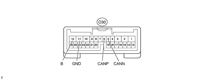
CAN COMMUNICATION SYSTEM > TERMINALS OF ECU |
| JUNCTION CONNECTOR |
NO. 1 JUNCTION CONNECTOR
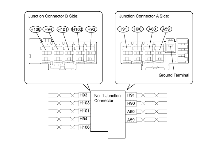
| Junction Connector A Side | Color (CANH Side) | Color (CANL Side) |
| Combination meter ECU (H91)*1*2 | SB | W |
| No. 4 junction connector (H91)*1*3 | SB | W |
| Center airbag sensor (H90) | BR | W |
| Skid control ECU (A59) | B | W |
| Distance control ECU (A60)*4 | BE | W |
| Junction Connector B Side | Color (CANH Side) | Color (CANL Side) |
| DLC3 (H93) | V | W |
| Main body ECU (H103)*1 | L | W |
| No. 2 junction connector (H101) | R | W |
| Steering angle sensor (H94) | G | W |
| Power steering ECU (H106) | GR | W |
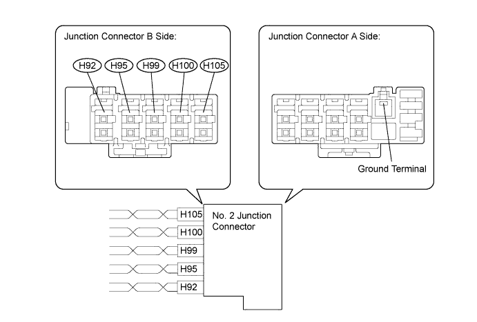
NO. 2 JUNCTION CONNECTOR

| Junction Connector A Side | Color (CANH Side) | Color (CANL Side) |
| Bus buffer ECU (H105) | P | W |
| No. 1 junction connector (H100) | R | W |
| ECM (H99) | GR | W |
| 4WD control ECU (H95) | O | W |
| Air conditioning amplifier (H92) | B | W |
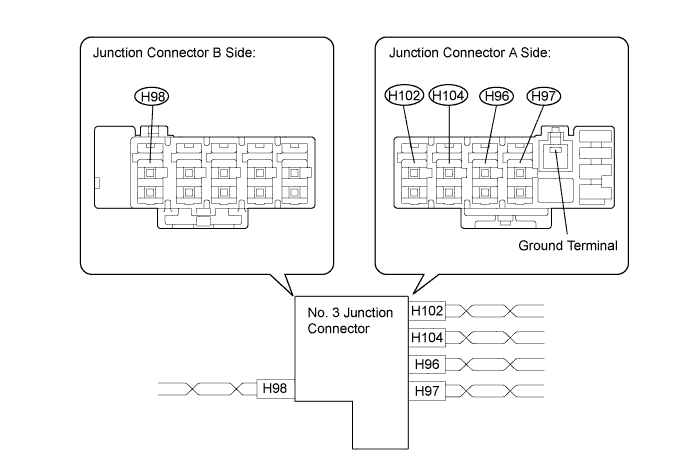
NO. 3 JUNCTION CONNECTOR

| Junction Connector A Side | Color (CANH Side) | Color (CANL Side) |
| Power seat control ECU (H97)*1 | GR | W |
| Multiplex tilt and telescopic ECU (H96)*1 | O | W |
| Main body ECU (H104)*1, *2, *3 | B | W |
| No. 4 junction connector (H104)*1, *2, *4 | B | W |
| Combination meter ECU (H102)*1, *2 | Y | W |
| Junction Connector B Side | Color (CANH Side) | Color (CANL Side) |
| Outer mirror control ECU (H98)*1 | LG | W |
![]() |
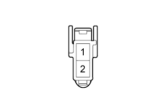
TERMINALS OF CONNECTORS FOR JUNCTION CONNECTOR (No. 1, No. 2 and No. 3)
| Terminal | Terminal Symbol |
| 1 | CANH |
| 2 | CANL |
NO. 4 JUNCTION CONNECTOR (FRONT OF THE VEHICLE)
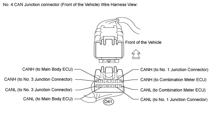
| Terminal No. (Symbol) | Wiring Color | Destination |
| O41-1 (CANH) | SB | Combination meter ECU (CANH)*1, *4 |
| O41-7 (CANL) | W | Combination meter ECU (CANL)*1, *4 |
| O41-2 (CANH) | L | No. 1 junction connector*1 |
| O41-8 (CANL) | W | No. 1 junction connector*1 |
| O41-5 (CANH) | B | Main body ECU (CANH)*2, *3 |
| O41-11 (CANL) | W | Main body ECU (CANL)*2, *3 |
| O41-6 (CANH) | P | No. 3 junction connector*2, *3 |
| O41-12 (CANL) | W | No. 3 junction connector*2, *3 |
NO. 4 JUNCTION CONNECTOR (REAR OF THE VEHICLE)
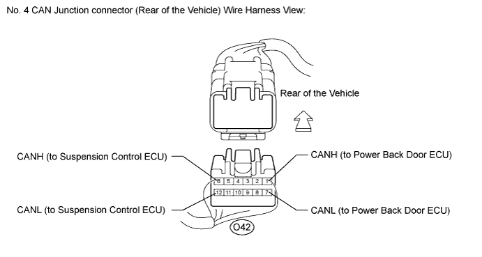
| Terminal No. (Symbol) | Wiring Color | Destination |
| O42-1 (CANH) | B | Power back door ECU (CANH)*2, *3 |
| O42-7 (CANL) | W | Power back door ECU (CANL)*2, *3 |
| O42-6 (CANH) | B | Suspension control ECU (CANH)*1, *4 |
| O42-12 (CANL) | W | Suspension control ECU (CANL)*1, *4 |
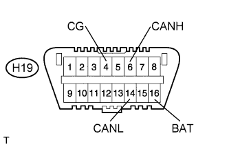
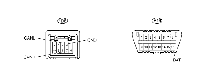
| CHECK DLC3 |
![]() |
Measure the resistance according to the value(s) in the table below.
| Terminal No. (Symbol) | Wiring Color | Switch Condition | Specified Condition |
| H19-6 (CANH) - H19-14 (CANL) | V - W | Ignition switch off | 54 to 69 Ω |
| H19-6 (CANH) - H19-4 (CG) | V - W-B | Ignition switch off | 200 Ω or higher |
| H19-14 (CANL) - H19-4 (CG) | W - W-B | Ignition switch off | 200 Ω or higher |
| H19-6 (CANH) - H19-16 (BAT) | V - P | Ignition switch off | 6 kΩ or higher |
| H19-14 (CANL) - H19-16 (BAT) | W - P | Ignition switch off | 6 kΩ or higher |
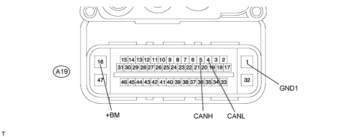
| CHECK SKID CONTROL ECU |

Disconnect the A19 ECU connector.
Measure the resistance according to the value(s) in the table below.
| Terminal No. (Symbol) | Wiring Color | Switch Condition | Specified Condition |
| A19-5 (CANH) - A19-4 (CANL) | B - W | Ignition switch off | 54 to 69 Ω |
| A19-5 (CANH) - A19-1 (GND1) | B - W-B | Ignition switch off | 200 Ω or higher |
| A19-4 (CANL) - A19-1 (GND1) | W - W-B | Ignition switch off | 200 Ω or higher |
| A19-5 (CANH) - A19-16 (+BM) | B - L | Ignition switch off | 6 kΩ or higher |
| A19-4 (CANL) - A19-16 (+BM) | W - L | Ignition switch off | 6 kΩ or higher |
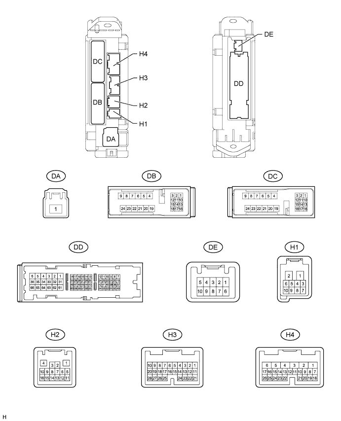
| CHECK MAIN BODY ECU |

Disconnect the H2, DB and DD ECU connectors.
Measure the resistance according to the value(s) in the table below.
| Terminal No. (Symbol) | Wiring Color | Switch Condition | Specified Condition |
| H2-5 (CANH) - H2-6 (CANL)*1 | L - W | Ignition switch off | 54 to 69 Ω |
| H2-5 (CANH) - DD-62 (GND1)*1 | L - W-B | Ignition switch off | 200 Ω or higher |
| H2-6 (CANL) - DD-62 (GND1)*1 | W - W-B | Ignition switch off | 200 Ω or higher |
| H2-5 (CANH) - DB-13 (BECU)*1 | L - GR | Ignition switch off | 6 kΩ or higher |
| H2-6 (CANL) - DB-13 (BECU)*1 | W - GR | Ignition switch off | 6 kΩ or higher |
| H2-16 (CANP) - H2-15 (CANN)*2 | B - W | Ignition switch off | 108 to 132 Ω |
| H2-16 (CANP) - DD-62 (GND1)*2 | B - W-B | Ignition switch off | 200 Ω or higher |
| H2-15 (CANN) - DD-62 (GND1)*2 | W - W-B | Ignition switch off | 200 Ω or higher |
| H2-16 (CANP) - DB-13 (BECU)*2 | B - GR | Ignition switch off | 6 kΩ or higher |
| H2-15 (CANN) - DB-13 (BECU)*2 | W - GR | Ignition switch off | 6 kΩ or higher |
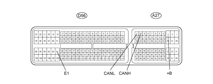
| CHECK ECM |

Disconnect the A27 and D56 ECM connector.
Measure the resistance according to the value(s) in the table below.
| Terminal No. (Symbol) | Wiring Color | Switch Condition | Specified Condition |
| A27-10 (CANH) - A27-11 (CANL) | GR - W | Ignition switch off | 108 to 132 Ω |
| A27-10 (CANH) - D56-81 (E1) | GR - BR | Ignition switch off | 200 Ω or higher |
| A27-11 (CANL) - D56-81 (E1) | W - BR | Ignition switch off | 200 Ω or higher |
| A27-10 (CANH) - A27-3 (+B) | GR - GR | Ignition switch off | 6 kΩ or higher |
| A27-11 (CANL) - A27-3 (+B) | W - GR | Ignition switch off | 6 kΩ or higher |
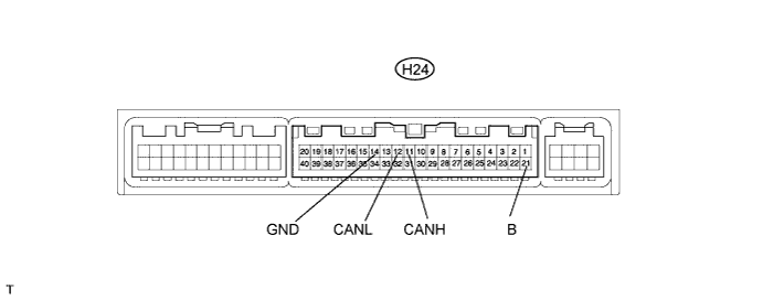
| CHECK AIR CONDITIONING AMPLIFIER |

Disconnect the H24 ECU connector.
Measure the resistance according to the value(s) in the table below.
| Terminal No. (Symbol) | Wiring Color | Switch Condition | Specified Condition |
| H24-11 (CANH) - H24-12 (CANL) | B - W | Ignition switch off | 54 to 69 Ω |
| H24-11 (CANH) - H24-14 (GND) | B - W-B | Ignition switch off | 200 Ω or higher |
| H24-12 (CANL) - H24-14 (GND) | W - W-B | Ignition switch off | 200 Ω or higher |
| H24-11 (CANH) - H24-21 (B) | B - R | Ignition switch off | 6 kΩ or higher |
| H24-12 (CANL) - H24-21 (B) | W - R | Ignition switch off | 6 kΩ or higher |
| CHECK CENTER AIRBAG SENSOR |

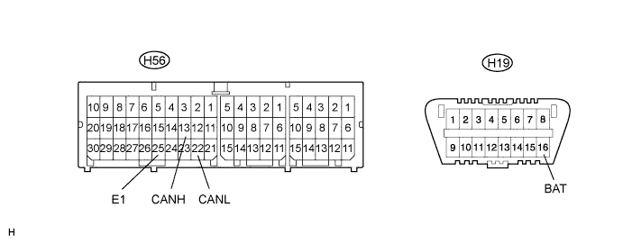
Disconnect the H56 ECU connector.
Measure the resistance according to the value(s) in the table below.
| Terminal No. (Symbol) | Wiring Color | Switch Condition | Specified Condition |
| H56-13 (CANH) - H56-22 (CANL) | BR - W | Ignition switch off | 54 to 69 Ω |
| H56-13 (CANH) - H56-25 (E1) | BR - W-B | Ignition switch off | 200 Ω or higher |
| H56-22 (CANL) - H56-25 (E1) | W - W-B | Ignition switch off | 200 Ω or higher |
| H56-13 (CANH) - H19-16 (BAT) | BR - P | Ignition switch off | 6 kΩ or higher |
| H56-22 (CANL) - H19-16 (BAT) | W - P | Ignition switch off | 6 kΩ or higher |
| CHECK COMBINATION METER ECU |

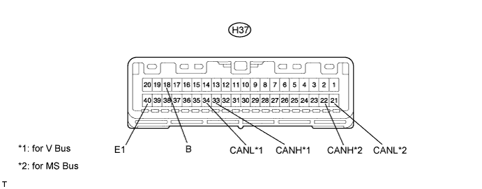
Disconnect the H37 ECU connector.
Measure the resistance according to the value(s) in the table below.
| Terminal No. (Symbol) | Wiring Color | Switch Condition | Specified Condition |
| H37-33 (CANH) - H37-34 (CANL)*1 | SB - W | Ignition switch off | 108 to 132 Ω |
| H37-33 (CANH) - H37-40 (E1)*1 | SB - W-B | Ignition switch off | 200 Ω or higher |
| H37-34 (CANL) - H37-40 (E1)*1 | W - W-B | Ignition switch off | 200 Ω or higher |
| H37-33 (CANH) - H37-18 (B)*1 | SB - LG | Ignition switch off | 6 kΩ or higher |
| H37-34 (CANL) - H37-18 (B)*1 | W - LG | Ignition switch off | 6 kΩ or higher |
| H37-22 (CANH) - H37-21 (CANL)*2 | Y - W | Ignition switch off | 108 to 132 Ω |
| H37-22 (CANH) - H37-40 (E1)*2 | Y - W-B | Ignition switch off | 200 Ω or higher |
| H37-21 (CANL) - H37-40 (E1)*2 | W - W-B | Ignition switch off | 200 Ω or higher |
| H37-22 (CANH) - H37-18 (B)*2 | Y - LG | Ignition switch off | 6 kΩ or higher |
| H37-21 (CANL) - H37-18 (B)*2 | W - LG | Ignition switch off | 6 kΩ or higher |
| CHECK STEERING ANGLE SENSOR |

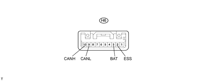
Disconnect the H6 sensor connector.
Measure the resistance according to the value(s) in the table below.
| Terminal No. (Symbol) | Wiring Color | Switch Condition | Specified Condition |
| H6-10 (CANH) - H6-9 (CANL) | G - W | Ignition switch off | 54 to 69 Ω |
| H6-10 (CANH) - H6-2 (ESS) | G - W-B | Ignition switch off | 200 Ω or higher |
| H6-9 (CANL) - H6-2 (ESS) | W - W-B | Ignition switch off | 200 Ω or higher |
| H6-10 (CANH) - H6-3 (BAT) | G - R | Ignition switch off | 6 kΩ or higher |
| H6-9 (CANL) - H6-3 (BAT) | W - R | Ignition switch off | 6 kΩ or higher |
| CHECK 4WD CONTROL ECU |

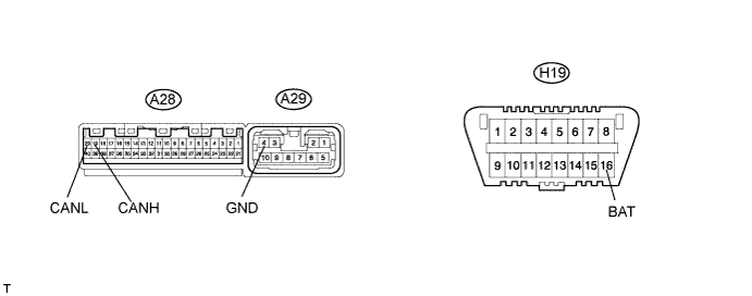
Disconnect the A28 and A29 ECU connectors.
Measure the resistance according to the value(s) in the table below.
| Terminal No. (Symbol) | Wiring Color | Switch Condition | Specified Condition |
| A28-19 (CANH) - A28-20 (CANL) | BE - W | Ignition switch off | 54 to 69 Ω |
| A28-19 (CANH) - A29-4 (GND) | BE - W-B | Ignition switch off | 200 Ω or higher |
| A28-20 (CANL) - A29-4 (GND) | W - W-B | Ignition switch off | 200 Ω or higher |
| A28-19 (CANH) - H19-16 (BAT) | BE - P | Ignition switch off | 6 kΩ or higher |
| A28-20 (CANL) - H19-16 (BAT) | W - P | Ignition switch off | 6 kΩ or higher |
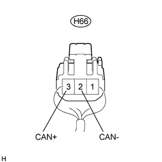
| CHECK BUS BUFFER ECU |
![]() |
Disconnect the H66 ECU connector.
Measure the resistance according to the value(s) in the table below.
| Terminal No. (Symbol) | Wiring Color | Switch Condition | Specified Condition |
| H66-3 (CAN+) - H66-2 (CAN-) | P - W | Ignition switch off | 54 to 69 Ω |
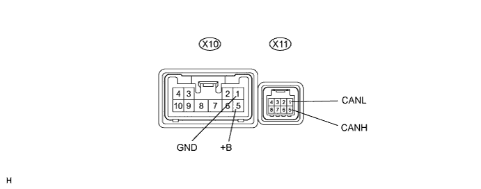
| CHECK POWER SEAT CONTROL ECU |

Disconnect the X10 and X11 ECU connectors.
Measure the resistance according to the value(s) in the table below.
| Terminal No. (Symbol) | Wiring Color | Switch Condition | Specified Condition |
| X11-5 (CANH) - X11-1 (CANL) | GR - W | Ignition switch off | 54 to 69 Ω |
| X11-5 (CANH) - X10-1 (GND) | GR - W-B | Ignition switch off | 200 Ω or higher |
| X11-1 (CANL) - X10-1 (GND) | W - W-B | Ignition switch off | 200 Ω or higher |
| X11-5 (CANH) - X10-5 (+B) | GR - L | Ignition switch off | 6 kΩ or higher |
| X11-1 (CANL) - X10-5 (+B) | W - L | Ignition switch off | 6 kΩ or higher |
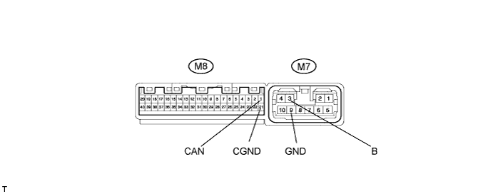
| CHECK OUTER MIRROR CONTROL ECU |

Disconnect the M7 and M8 ECU connectors.
Measure the resistance according to the value(s) in the table below.
| Terminal No. (Symbol) | Wiring Color | Switch Condition | Specified Condition |
| M8-1 (CAN) - M8-21 (CGND) | LG - W | Ignition switch off | 54 to 69 Ω |
| M8-1 (CAN) - M7-9 (GND) | LG - W-B | Ignition switch off | 200 Ω or higher |
| M8-21 (CGND) - M7-9 (GND) | W - W-B | Ignition switch off | 200 Ω or higher |
| M8-1 (CAN) - M7-3 (B) | LG - R | Ignition switch off | 6 kΩ or higher |
| M8-21 (CGND) - M7-3 (B) | W - R | Ignition switch off | 6 kΩ or higher |
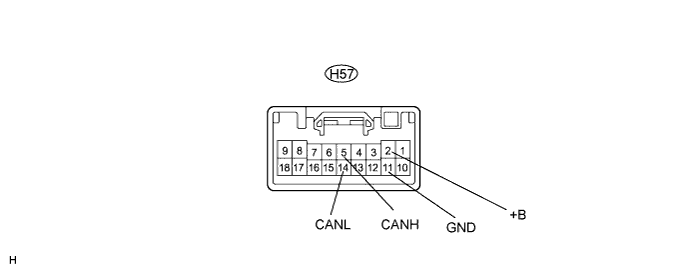
| CHECK MULTIPLEX TILT AND TELESCOPIC ECU |

Disconnect the H57 ECU connector.
Measure the resistance according to the value(s) in the table below.
| Terminal No. (Symbol) | Wiring Color | Switch Condition | Specified Condition |
| H57-5 (CANH) - H57-14 (CANL) | O - W | Ignition switch off | 54 to 69 Ω |
| H57-5 (CANH) - H57-11 (GND) | O - W-B | Ignition switch off | 200 Ω or higher |
| H57-14 (CANL) - H57-11 (GND) | W - W-B | Ignition switch off | 200 Ω or higher |
| H57-5 (CANH) - H57-2 (+B) | O - V | Ignition switch off | 6 kΩ or higher |
| H57-14 (CANL) - H57-2 (+B) | W - V | Ignition switch off | 6 kΩ or higher |
| CHECK DISTANCE CONTROL ECU |

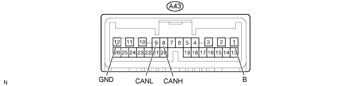
Disconnect the A43 ECU connector.
Measure the resistance according to the value(s) in the table below.
| Terminal No. (Symbol) | Wiring Color | Switch Condition | Specified Condition |
| A43-8 (CANH) - A43-9 (CANL) | BE - W | Ignition switch off | 54 to 69 Ω |
| A43-8 (CANH) - A43-12 (GND) | BE - BR | Ignition switch off | 200 Ω or higher |
| A43-9 (CANL) - A43-12 (GND) | W - BR | Ignition switch off | 200 Ω or higher |
| A43-8 (CANH) - A43-1 (B) | BE - BE | Ignition switch off | 6 kΩ or higher |
| A43-9 (CANL) - A43-1 (B) | W - BE | Ignition switch off | 6 kΩ or higher |
| CHECK POWER STEERING ECU |

Disconnect the H38 ECU connector.
Measure the resistance according to the value(s) in the table below.
| Terminal No. (Symbol) | Wiring Color | Switch Condition | Specified Condition |
| H38-8 (CANH) - H38-3 (CANL) | GR - W | Ignition switch off | 54 to 69 Ω |
| H38-8 (CANH) - H38-2 (GND) | GR - W-B | Ignition switch off | 200 Ω or higher |
| H38-3 (CANL) - H38-2 (GND) | W - W-B | Ignition switch off | 200 Ω or higher |
| H38-8 (CANH) - H19-16 (BAT) | GR - P | Ignition switch off | 6 kΩ or higher |
| H38-3 (CANL) - H19-16 (BAT) | W - P | Ignition switch off | 6 kΩ or higher |
| CHECK SUSPENSION CONTROL ECU |
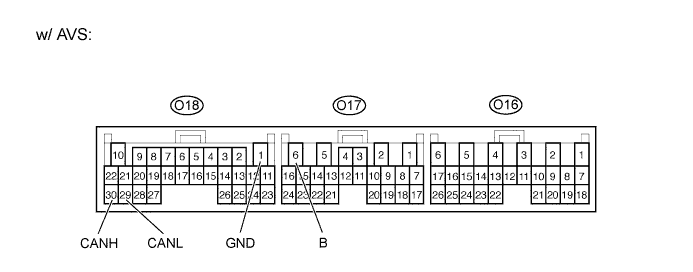
with AVS

Disconnect the O17 and O18 ECU connector.
Measure the resistance according to the value(s) in the table below.
| Terminal No. (Symbol) | Wiring Color | Switch Condition | Specified Condition |
| O18-30 (CANH) - O18-29 (CANL) | B - W | Ignition switch off | 54 to 69 Ω |
| O18-30 (CANH) - O18-1 (GND) | B - W-B | Ignition switch off | 200 Ω or higher |
| O18-29 (CANL) - O18-1 (GND) | W - W-B | Ignition switch off | 200 Ω or higher |
| O18-30 (CANH) - O17-6 (B) | B - SB | Ignition switch off | 6 kΩ or higher |
| O18-29 (CANL) - O17-6 (B) | W - SB | Ignition switch off | 6 kΩ or higher |
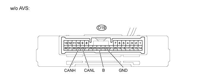
without AVS

Disconnect the O19 ECU connector.
Measure the resistance according to the value(s) in the table below.
| Terminal No. (Symbol) | Wiring Color | Switch Condition | Specified Condition |
| O19-29 (CANH) - O19-28 (CANL) | B - W | Ignition switch off | 54 to 69 Ω |
| O19-29 (CANH) - O19-22 (GND) | B - W-B | Ignition switch off | 200 Ω or higher |
| O19-28 (CANL) - O19-22 (GND) | W - W-B | Ignition switch off | 200 Ω or higher |
| O19-29 (CANH) - O19-24 (B) | B - SB | Ignition switch off | 6 kΩ or higher |
| O19-28 (CANL) - O19-24 (B) | W - SB | Ignition switch off | 6 kΩ or higher |
| CHECK POWER BACK DOOR ECU |

Disconnect the O30 ECU connector.
Measure the resistance according to the value(s) in the table below.
| Terminal No. (Symbol) | Wiring Color | Switch Condition | Specified Condition |
| O30-6 (CANP) - O30-5 (CANN) | B - W | Ignition switch off | 54 to 69 Ω |
| O30-6 (CANP) - O30-11 (GND) | B - W-B | Ignition switch off | 200 Ω or higher |
| O30-5 (CANN) - O30-11 (GND) | W - W-B | Ignition switch off | 200 Ω or higher |
| O30-6 (CANP) - O30-12 (B) | B - L | Ignition switch off | 6 kΩ or higher |
| O30-5 (CANN) - O30-12 (B) | W - L | Ignition switch off | 6 kΩ or higher |