 |
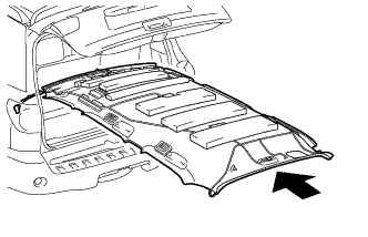
Place the roof headlining into the cabin as shown in the illustration.
- NOTICE:
- Be careful not to damage the roof headlining when placing it in the cabin.
ROOF HEADLINING > INSTALLATION |
| 1. INSTALL ROOF HEADLINING ASSEMBLY (w/o Rear Seat Entertainment System) |
|
Place the roof headlining into the cabin as shown in the illustration.
Install the washer hose.
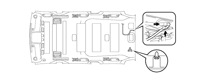
Engage the clip and install the roof headlining.
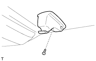 |
Install the visor holder with the screw.
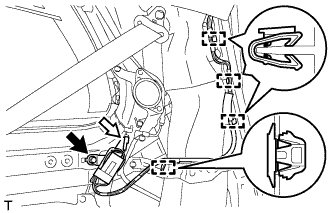 |
Engage the 4 clamps and install the amplifier antenna.
Install the bolt.
Connect the connector.
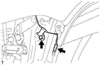 |
Install the bolt and amplifier antenna.
Connect the connector.
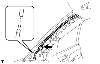 |
Install the washer hose and the amplifier antenna.
Connect the connector.
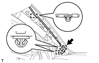 |
Engage the 3 clamps and install the roof wire.
Connect the connector.
| 2. INSTALL ROOF HEADLINING ASSEMBLY (w/ Rear Seat Entertainment System) |
|
Place the roof headlining into the cabin as shown in the illustration.
Install the washer hose.
Engage the clip and install the roof headlining.
|
Install the visor holder with the screw.
|
Engage the 4 clamps and install the amplifier antenna.
Install the bolt.
Connect the connector.
|
Install the bolt and amplifier antenna.
Connect the connector.
|
Install the washer hose and the amplifier antenna.
Connect the connector.
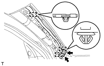 |
Engage the 3 clamps and install the roof wire.
Connect the 2 connectors.
| 3. INSTALL ROOF HEADLINING ASSEMBLY (w/ Sliding Roof) |
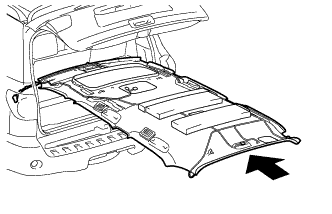 |
Place the roof headlining into the cabin as shown in the illustration.
Install the washer hose.
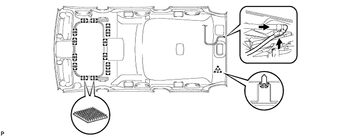
Engage the clip and 14 fasteners.
|
Engage the 4 clamps and install the amplifier antenna.
Install the bolt.
Connect the connector.
|
Install the bolt and amplifier antenna.
Connect the connector.
|
Install the washer hose and the amplifier antenna.
Connect the connector.
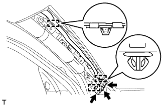 |
Engage the 3 clamps and install the roof wire.
Connect the 3 connectors.
| 4. INSTALL REAR VIEW INNER MIRROR STAY HOLDER COVER (w/ EC Mirror) |
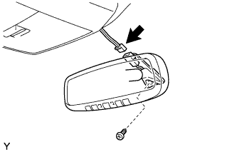 |
Using a T20 "TORX" socket wrench, install the inner rear view mirror with the screw.
Connect the connector.
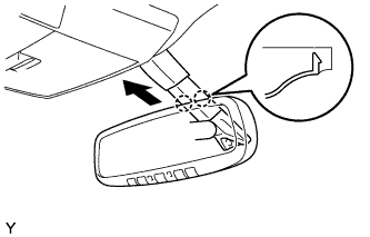 |
Attach the 2 claws to install the inner rear view mirror cover.
| 5. INSTALL ROOF HEADLINING REAR TRIM COVER LH |
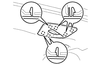 |
Engage the 6 claws and install the roof headlining rear trim cover LH.
| 6. INSTALL ASSIST GRIP PLUG |
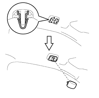 |
Install assist grip plug.
| 7. INSTALL ASSIST GRIP SUB-ASSEMBLY |
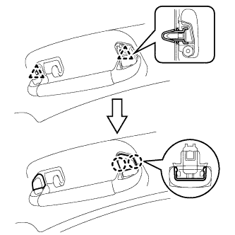 |
Install the 2 clips and 2 covers to the assist grip, as shown in the illustration.
Install the assist grip.
| 8. INSTALL VISOR ASSEMBLY RH (w/ Illumination) |
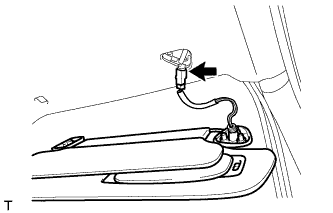 |
Connect the connector.
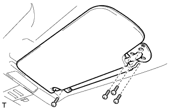 |
Install the 4 screws and the visor.
| 9. INSTALL VISOR ASSEMBLY LH (w/ Illumination) |
| 10. INSTALL VISOR ASSEMBLY RH (w/o Illumination) |
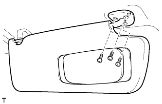 |
Install the 3 screws and the visor.
| 11. INSTALL VISOR ASSEMBLY LH (w/o Illumination) |
| 12. INSTALL VISOR BRACKET COVER RH |
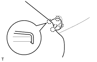 |
Attach the 4 claws to install the visor bracket cover.
| 13. INSTALL VISOR BRACKET COVER LH |
| 14. INSTALL NO. 2 ROOM LIGHT ASSEMBLY |
Connect the connector.
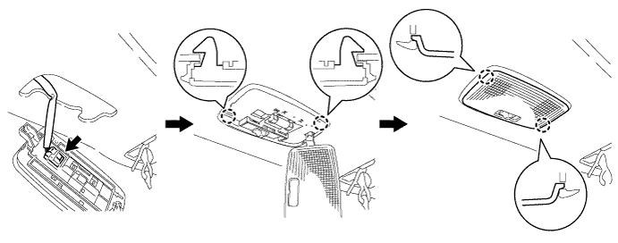
Engage the 2 claws and install the No. 2 room light.
Engage the 2 claws and install the lens.
| 15. INSTALL NO. 1 ROOM LIGHT ASSEMBLY |
Connect the connector.
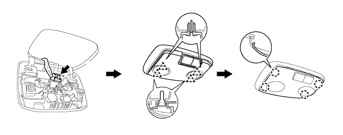
Engage the 4 clips to install the No. 1 room light.
Engage the 4 claws to install the lens.
| 16. INSTALL NO. 1 ROOM LIGHT ASSEMBLY (w/ Rear Seat Entertainment System) |
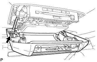 |
Connect the connector.
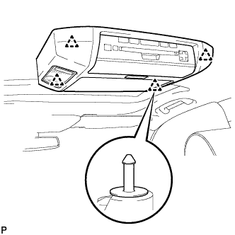 |
Engage the 4 clips to install the No. 1 room light.
| 17. INSTALL ROOF CONSOLE BOX ASSEMBLY |
for Short Type:
Install the roof console box .
for Long Type:
Install the roof console box .
| 18. INSTALL REAR WINDOW NO. 2 SIDE GARNISH ASSEMBLY RH |
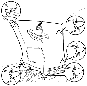 |
Engage the 5 clips and install the rear window No. 2 side garnish assembly RH.
Install the bolt.
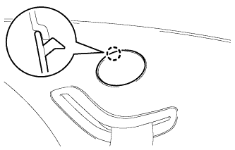 |
Engage the claw and install the cover.
| 19. INSTALL REAR WINDOW NO. 2 SIDE GARNISH ASSEMBLY LH (w/o Power Back Door) |
| 20. INSTALL REAR WINDOW NO. 2 SIDE GARNISH ASSEMBLY LH (w/ Power Back Door) |
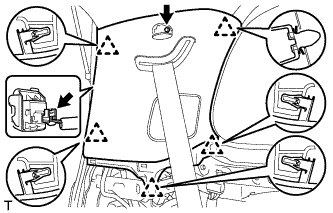 |
Connect the connector.
Engage the 5 clips and install the rear window No. 2 side garnish assembly LH.
Install the bolt.
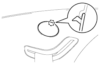 |
Engage the claw and install the cover.
| 21. INSTALL REAR WINDOW SIDE GARNISH ASSEMBLY RH |
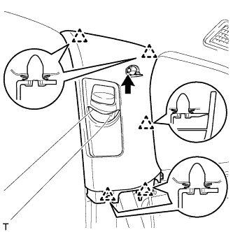 |
Pass the rear seat outer belt floor anchor through the quarter trim panel.
Engage the 5 clips and install the rear window side garnish.
Install the bolt.
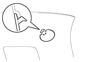 |
Engage the claw and install the cover.
| 22. INSTALL REAR WINDOW SIDE GARNISH ASSEMBLY LH |
| 23. INSTALL QUARTER TRIM PANEL ASSEMBLY RH |
Connect the connector.
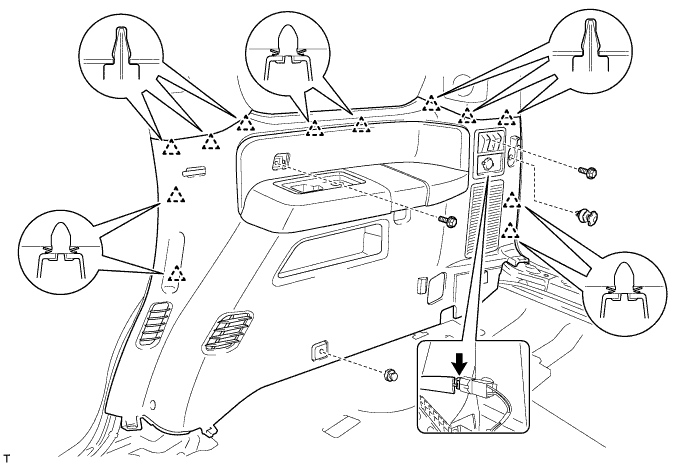
Engage the 12 clips and install the quarter trim panel assembly.
Install the 2 bolts.
Engage the 2 clips.
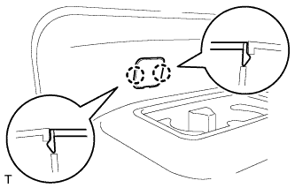 |
Engage the 2 claws and install the cover.
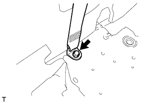 |
Install the outer lap belt anchor with bolt.
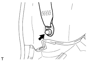 |
Install the outer lap belt anchor with bolt.
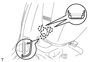 |
Engage the 3 claws to install the outer lap belt anchor cover.
| 24. INSTALL QUARTER TRIM PANEL ASSEMBLY LH |
Connect the connector.
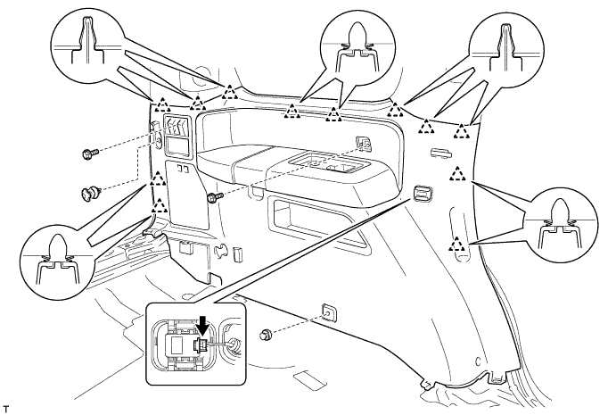
Engage the 12 clips to install the quarter trim panel.
Install the 2 bolts.
Engage the 2 clips.
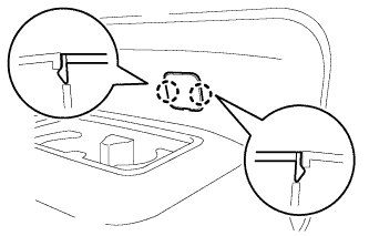 |
Engage the 2 claws and install the cover.
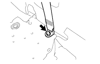 |
Install the outer lap belt anchor with bolt.
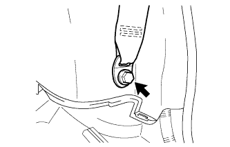 |
Install the outer lap belt anchor with bolt.
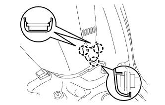 |
Engage the 3 claws to install the outer lap belt anchor cover.
| 25. INSTALL QUARTER TRIM PANEL ASSEMBLY RH (for Power Seat) |
Connect the 3 connectors.
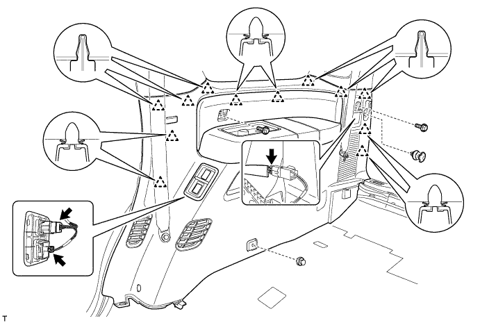
Engage the 12 clips to install the quarter trim panel.
Install the 2 bolts.
Engage the 2 clips.
|
Engage the 2 claws and install the cover.
|
Install the outer lap belt anchor with bolt.
|
Install the outer lap belt anchor with bolt.
|
Engage the 3 claws to install the outer lap belt anchor cover.
| 26. INSTALL QUARTER TRIM PANEL ASSEMBLY LH (for Power Seat) |
Connect the 5 connectors.
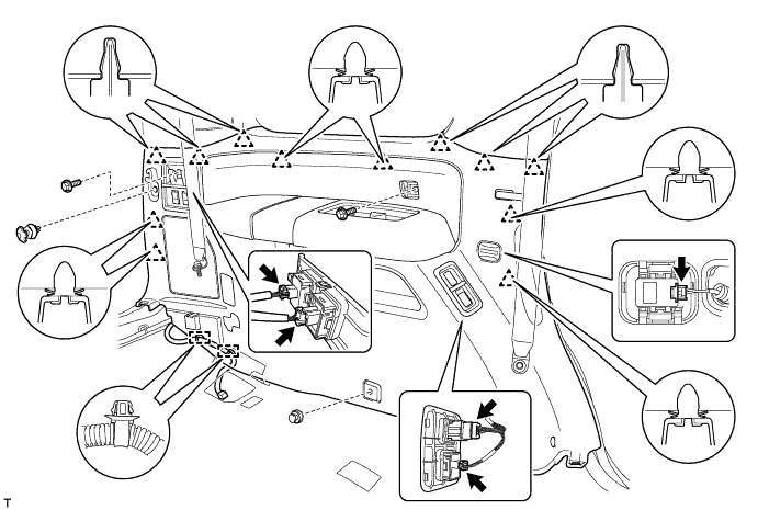
Engage the 12 clips to install the quarter trim panel.
Install the 2 bolts.
Engage the 2 clamps and install the wire harness.
Engage the 2 clips.
|
Engage the 2 claws and install the cover.
|
Install the outer lap belt anchor with bolt.
|
Install the outer lap belt anchor with bolt.
|
Engage the 3 claws to install the outer lap belt anchor cover.
| 27. INSTALL REAR FLOOR MAT SUPPORT PLATE |
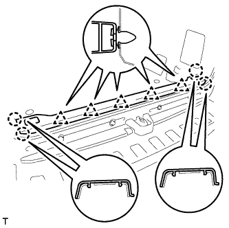 |
Engage the 5 clips and the 4 claws, and install the rear floor mat support plate.
| 28. INSTALL ROPE HOOK ASSEMBLY |
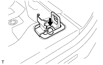 |
Install the rope hook with the bolt.
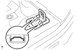 |
Engage the 2 claws and install the cover.
| 29. INSTALL CENTER PILLAR GARNISH RH |
Pass the front seat outer belt floor anchor through the center pillar garnish.
Engage the clip and the guide to install the center pillar garnish.
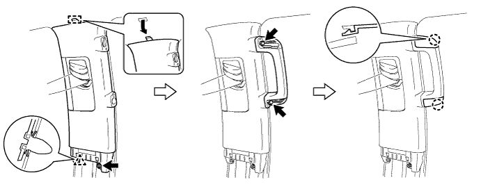
Install the bolt.
Install the assist grip with the 2 bolts.
Engage the 2 claws to install the 2 assist grip plugs.
| 30. INSTALL CENTER PILLAR GARNISH LH |
| 31. INSTALL LOWER CENTER PILLAR GARNISH RH |
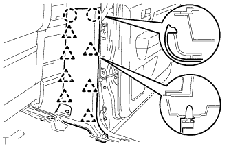 |
Engage the 7 clips and 2 claws to install the center pillar garnish.
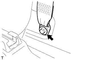 |
Install the front seat outer belt assembly RH with the bolt.
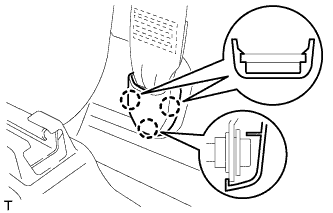 |
Engage the 3 claws to install the cover.
| 32. INSTALL LOWER CENTER PILLAR GARNISH LH |
| 33. INSTALL FRONT PILLAR GARNISH RH |
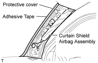 |
Remove the protective cover.
Engage the claw to install the front pillar garnish.
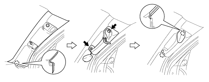
Install the assist grip with the 2 bolts.
Engage the 2 claws to install the 2 assist grip plugs.
| 34. INSTALL FRONT PILLAR GARNISH LH |
| 35. INSTALL REAR DOOR OPENING TRIM WEATHERSTRIP RH |
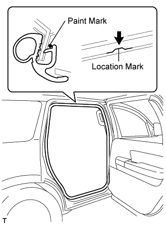 |
Align the location mark with the paint mark first, and install the rear door opening trim weatherstrip, as shown in the illustration.
| Area | Color |
| RH side | Pink |
| LH side | Purple |
| 36. INSTALL REAR DOOR OPENING TRIM WEATHERSTRIP LH |
| 37. INSTALL REAR DOOR SCUFF PLATE RH |
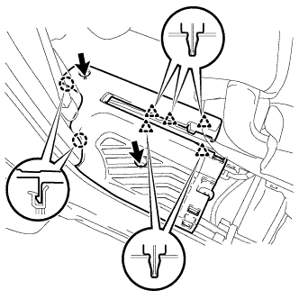 |
Engage the 2 claws and 5 clips to install the rear door scuff plate.
Install the 2 bolts.
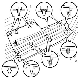 |
Engage the 6 claws and the 5 clips and the 2 guides, and install the rear door scuff plate.
Install the screw.
| 38. INSTALL REAR DOOR SCUFF PLATE LH |
| 39. INSTALL REAR FLOOR STEP NO. 1 COVER |
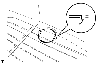 |
Engage the 2 claws and install the rear floor step No. 1 cover.
| 40. INSTALL REAR FLOOR STEP NO. 2 COVER |
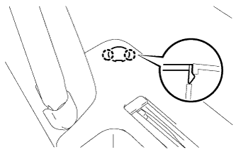 |
Engage the 2 claws and the install the rear floor step No. 2 cover.
| 41. INSTALL REAR SEAT CUSHION HINGE LOWER COVER RH |
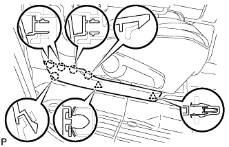 |
Engage the 2 clips and the 5 claws, and install the rear cushion hinge lower cover RH.
| 42. INSTALL REAR SEAT CUSHION HINGE LOWER COVER LH |
| 43. INSTALL FRONT DOOR OPENING TRIM WEATHERSTRIP RH |
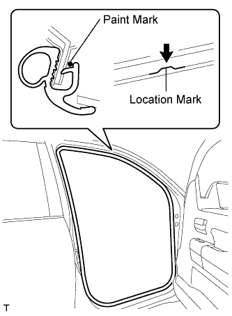 |
Align the location mark with the paint mark first, and install the front door opening trim weatherstrip, as shown in the illustration.
| Area | Color |
| RH side | White |
| LH side | Yellow |
| 44. INSTALL FRONT DOOR OPENING TRIM WEATHERSTRIP LH |
| 45. INSTALL COWL SIDE TRIM BOARD RH |
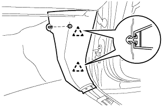 |
Engage the 2 clips to install the cowl side trim board.
Install the clip.
| 46. INSTALL COWL SIDE TRIM BOARD LH |
| 47. INSTALL FRONT DOOR SCUFF PLATE RH |
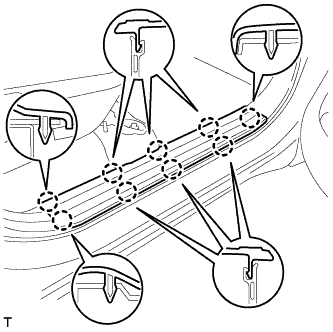 |
Engage the 9 claws to install the scuff plate.
| 48. INSTALL FRONT DOOR SCUFF PLATE LH |
| 49. INSTALL REAR NO. 2 SEAT ASSEMBLY RH |
for Manual seat:
Install the rear No. 2 seat assembly RH .
for Power seat:
Install the rear No. 2 seat assembly RH .
| 50. INSTALL REAR NO. 2 SEAT ASSEMBLY LH |
for Manual seat:
Install the rear No. 2 seat assembly LH .
for Power seat:
Install the rear No. 2 seat assembly LH .
| 51. INSTALL DECK BOARD BRACKET |
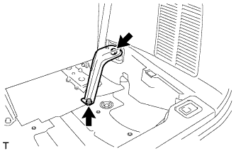 |
Install the deck board bracket with the 2 bolts.
| 52. INSTALL DECK BOARD REINFORCEMENT SUB-ASSEMBLY |
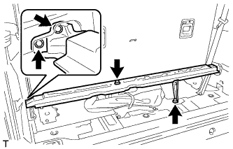 |
Install the deck board reinforcement with the 4 bolts.
| 53. INSTALL NO. 1 DECK BOARD SUB-ASSEMBLY |
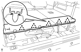 |
Engage the 5 clips and install the No. 1 deck board.
| 54. INSTALL ROPE HOOK ASSEMBLY |
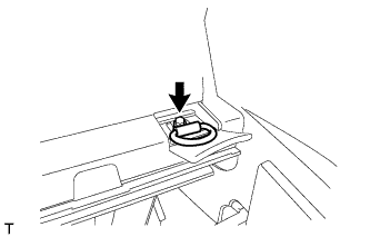 |
Install the rope hook with the bolt.
| 55. INSTALL LUGGAGE COMPARTMENT TRIM BOX |
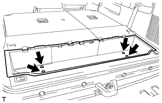 |
Install the luggage compartment trim box with the 4 bolts.
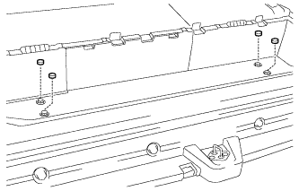 |
Install the 4 caps.
| 56. INSTALL NO. 2 DECK BOARD SUB-ASSEMBLY |
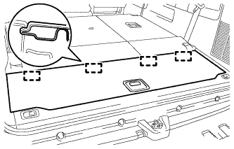 |
Engage the 4 guides and install the No. 2 deck board.
| 57. CONNECT CABLE TO NEGATIVE BATTERY TERMINAL |
| 58. INSPECT SRS WARNING LIGHT |
Inspect the SRS warning light (Click here).