 |
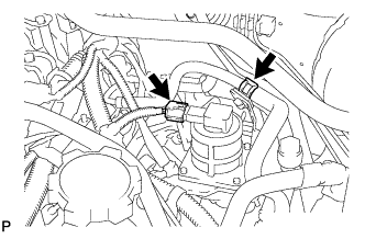
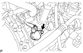
Disconnect the air switching valve assembly connector.
ENGINE UNIT > REMOVAL |
| 1. REMOVE NO. 2 AIR TUBE HOSE |
|
Disconnect the air switching valve assembly connector.
Disconnect the fuel hose clamp.
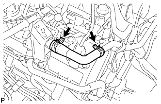 |
Remove the No. 2 air hose.
| 2. REMOVE AIR SWITCHING VALVE ASSEMBLY (for Bank 1) |
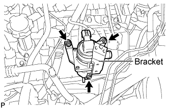 |
Remove the 3 nuts and air switching valve assembly.
| 3. REMOVE AIR SWITCHING VALVE ASSEMBLY (for Bank 2) |
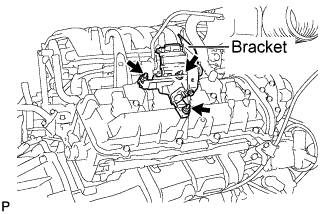 |
Remove the 3 nuts and air switching valve assembly.
| 4. REMOVE IGNITION COIL ASSEMBLY |
 |
Disconnect the 8 ignition coil assembly connectors.
Remove the 8 bolts and pull out the 8 ignition coil assemblies.
| 5. REMOVE NO. 3 WATER BY-PASS PIPE |
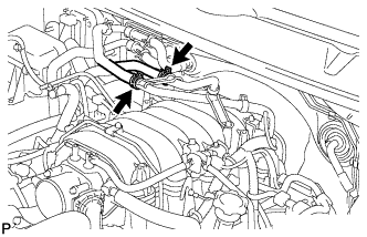 |
Disconnect the 2 water hoses from the No. 2 water by-pass pipe.
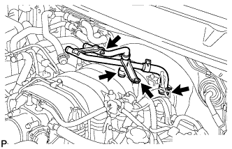 |
Remove the 2 bolts.
Disconnect the 2 water hoses and remove the No. 2 water by-pass pipe.
| 6. REMOVE INTAKE MANIFOLD |
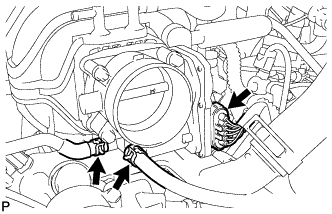 |
Disconnect the throttle body connector.
Disconnect the 2 water by-pass hoses from the throttle body assembly.
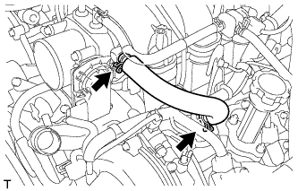 |
Loose the 2 clamps and remove the No. 1 ventilation hose.
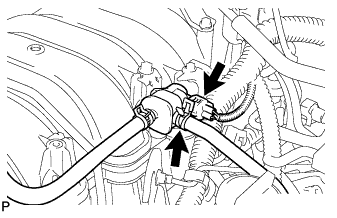 |
Disconnect the purge VSV connector.
Disconnect the purge line hose from the purge VSV.
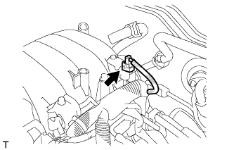 |
Disconnect the vacuum switching valve assembly (for ACIS) connector.
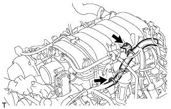 |
Disconnect the wire harness clamp from the engine hanger.
Remove the bolt and wire harness bracket from the intake manifold assembly.
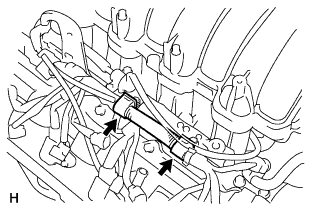 |
Disconnect the 2 wire clamps.
Disconnect the 8 injector connectors.
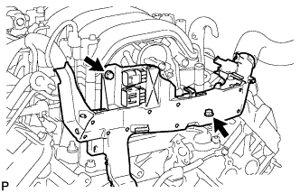 |
Remove the 2 bolts and separate the engine wire protector.
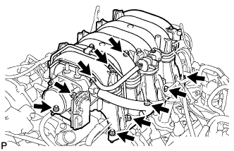 |
Remove the 6 bolts, 4 nuts, intake manifold assembly and 2 gaskets.
| 7. REMOVE NO. 3 AIR TUBE HOSE |
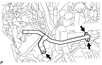 |
Remove the 3 bolts, No. 3 air tube hose and gasket.
| 8. REMOVE WATER BY-PASS PIPE SUB-ASSEMBLY |
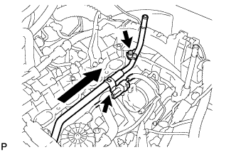 |
Disconnect the connector clamp.
Remove the bolt.
Pull out the water by-pass pipe sub-assembly.
Remove the O-ring from the water by-pass pipe sub-assembly.
| 9. REMOVE NO. 4 AIR INJECTION SYSTEM HOSE |
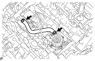 |
Loosen the 2 clips and remove the No. 1 air injection system hose.
| 10. REMOVE AIR PUMP ASSEMBLY |
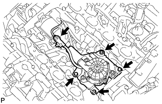 |
Disconnect the air pump assembly connector.
Remove the 2 bolts, 2 nuts and air pump assembly.
| 11. REMOVE STARTER ASSEMBLY |
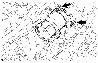 |
Remove the 2 bolts holding the starter to the cylinder block.
Disconnect the starter from the cylinder block.
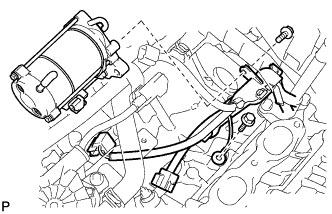 |
Remove the bolt and disconnect the engine wire protector from the starter assembly.
Remove the bolt and ground wire.
Disconnect the starter assembly connector.
Remove the nut and disconnect the starter assembly wire.
Remove the starter assembly.
| 12. REMOVE INLET WATER HOUSING |
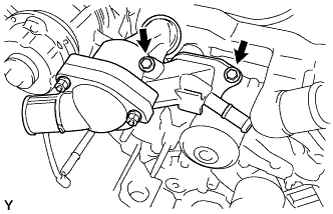 |
Disconnect the water by-pass hose from the inlet water housing.
Remove the 2 bolts and inlet water housing with water inlet.
Remove the O-ring from the inlet water housing.
| 13. REMOVE FRONT WATER BY-PASS JOINT |
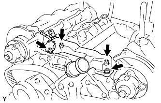 |
Remove the 4 nuts, water by-pass joint and 2 gaskets.
| 14. REMOVE REAR WATER BY-PASS JOINT |
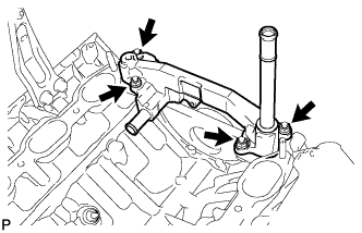 |
Disconnect the air hose and remove the 4 nuts, water by-pass joint and 2 gaskets.
| 15. REMOVE OIL COOLER PIPE |
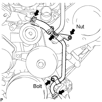 |
Remove the nut and bolt.
Disconnect the 3 water by-pass hose and remove the oil cooler pipe.
| 16. REMOVE NO. 2 WIRING HARNESS HEAT INSULATOR |
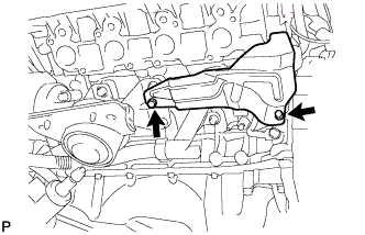 |
Remove the 2 bolts and heat insulator.
| 17. REMOVE FRONT ENGINE MOUNTING INSULATOR RH |
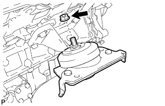 |
Remove the nut and mounting insulator.
| 18. REMOVE FRONT ENGINE MOUNTING INSULATOR LH |
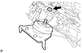 |
Remove the nut and mounting insulator.
| 19. REMOVE FRONT NO. 1 ENGINE MOUNTING BRACKET RH |
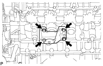 |
Remove the 4 bolts and mounting bracket.
| 20. REMOVE FRONT NO. 1 ENGINE MOUNTING BRACKET LH |
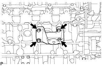 |
Remove the 4 bolts and mounting bracket.
| 21. REMOVE CAMSHAFT TIMING OIL CONTROL VALVE ASSEMBLY RH (for Bank 2) |
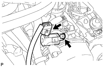 |
Disconnect the camshaft timing oil control valve assembly connector.
Remove the bolt and camshaft timing oil control valve assembly.
Remove the O-ring from the camshaft timing oil control valve assembly.
| 22. REMOVE CAMSHAFT TIMING OIL CONTROL VALVE ASSEMBLY LH (for Bank 1) |
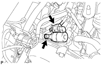 |
Disconnect the camshaft timing oil control valve assembly connector.
Remove the bolt and camshaft timing oil control valve assembly.
Remove the O-ring from the camshaft timing oil control valve assembly.
| 23. REMOVE VVT SENSOR |
Disconnect the 2 VVT sensor connectors.
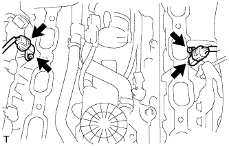 |
Remove the 2 bolts and remove the 2 VVT sensor connectors.
| 24. REMOVE KNOCK CONTROL SENSOR |
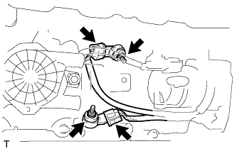 |
Disconnect the 2 knock sensor connectors.
Remove the 2 nuts and 2 knock sensors.
| 25. REMOVE CRANKSHAFT POSITION SENSOR |
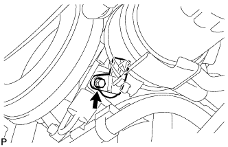 |
Disconnect the crankshaft position sensor connector.
Remove the bolt and crankshaft position sensor.
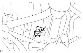
| 26. REMOVE VENTILATION VALVE SUB-ASSEMBLY |
 |