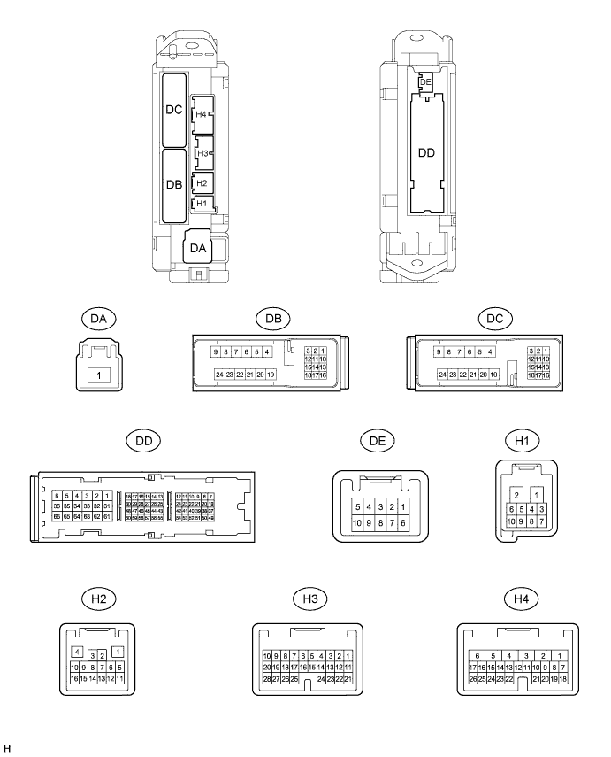
LIGHTING SYSTEM > TERMINALS OF ECU |
| CHECK MAIN BODY ECU |
Disconnect the DC, DD, H3, and H4 main body ECU connectors.
Measure the resistance according to the value(s) in the table below.
| Terminal No. (Symbol) | Wiring Color | Terminal Description | Condition | Specified Condition |
| DC-2 (LCTY) - Body ground | B*1 - Body ground G*2 - Body ground | Rear door courtesy light switch LH signal | Rear door LH open → closed | Below 1 Ω → 10 kΩ or higher |
| DD-62 (GND1, GND2) - Body ground | W-B - Body ground | Body ground | Always | Below 1 Ω |
| H3-21 (PCTY) - Body ground | O - Body ground | Front door courtesy light switch RH signal | Front door RH open → closed | Below 1 Ω → 10 kΩ or higher |
| H3-25 (RRCY) - Body ground | L - Body ground | Rear door courtesy light switch RH signal | Rear door RH open → closed | Below 1 Ω → 10 kΩ or higher |
| H4-24 (DCTY) - Body ground | BR - Body ground | Front door courtesy light switch LH signal | Front door LH open → closed | Below 1 Ω → 10 kΩ or higher |
Reconnect the DC, DD, H3 and H4 main body ECU connectors.
Measure the voltage according to the value(s) in the table below.
| Terminal No. (Symbol) | Wiring Color | Terminal Description | Condition | Specified Condition |
| DB-13 (BECU) - Body ground | GR - Body ground | BECU power supply | Always | 11 to 14 V |
| DD-43 (IG) - Body ground | LG - Body ground | IG signal | Ignition switch off → ON | Below 1 V → 11 to 14 V |
| DD-45 (ACC) - Body ground | O - Body ground | ACC signal | Ignition switch off → ACC | Below 1 V → 11 to 14 V |
| DD-51 (ILE) - Body ground | GR - Body ground | Illuminated entry system operate signal | Illuminated entry system off → on | 11 to 14 V → Below 1 V |
| H2-5 (CANH) - DD-62 (GND1, GND2) | L - W-B | CAN communication signal | Ignition switch ON | Pulse generation (See waveform 1) |
| H2-6 (CANL)- DD-62 (GND1, GND2) | W - W-B | CAN communication signal | Ignition switch ON | Pulse generation (See waveform 2) |
| H2-10 (LIN2) - DD-62 (GND1, GND2) | V - W-B | LIN communication signal | Ignition switch ON | Pulse generation |
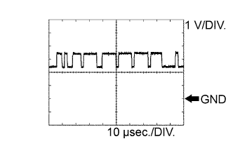 |
Waveform 1 (Reference) : Using an oscilloscope
| Terminal Name | CANH - GND1, GND2 |
| Tester Range | 1 V/DIV., 10 μsec./DIV. |
| Condition | Ignition switch ON |
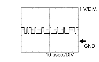 |
Waveform 2 (Reference) : Using an oscilloscope
| Terminal Name | CANL - GND1, GND2 |
| Tester Range | 1 V/DIV., 10 μsec./DIV. |
| Condition | Ignition switch ON |
| CHECK BACK DOOR ECU |
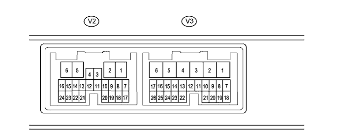
Disconnect the V2 and V3 back door ECU connectors.
Measure the voltage and resistance according to the value(s) in the table below.
| Terminal No. (Symbol) | Wiring Color | Terminal Description | Condition | Specified Condition |
| V2-7 (BECU) - Body ground | GR - Body ground | Battery power supply | Always | 11 to 14 V |
| V2-8 (SIG) - Body ground | Y - Body ground | IG power supply | Ignition switch off | Below 1 V |
| Ignition switch ON | 11 to 14 V | |||
| V2-6 (GND) - Body ground | W-B - Body ground | Ground | Always | Below 1 Ω |
| V3-10 (BDCY) - V3-20 (CTYE) | P - R | Back door courtesy light switch signal | Back door open | Below 1 Ω |
| Back door closed | 10 kΩ or higher |
Reconnect the V2 and V3 back door ECU connectors.
Measure the voltage and resistance according to the value(s) in the table below.
| Terminal No. (Symbol) | Wiring Color | Terminal Description | Condition | Specified Condition |
| V2-2 (LGLP) - V2-6 (GND) | LG - W-B | Illumination signal (to luggage compartment room light assembly) | Back door closed | 11 to 14 V |
| Back door open | Below 1 V | |||
| V2-16 (MPX1) - V2-6 (GND) | Y - W-B | LIN communication signal | Ignition switch ON | Pulse generation |
| V3-20 (CTYE) - V2-6 (GND) | R - W-B | Ground for back door courtesy light switch | Always | Below 1 Ω |