 |
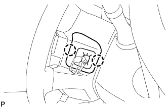
Using a screwdriver, remove the No. 2 steering wheel cover.
- HINT:
- Tape the screwdriver tip before use.
ACCESSORY METER > REMOVAL |
| 1. DISCONNECT CABLE FROM NEGATIVE BATTERY TERMINAL |
| 2. REMOVE LOWER NO. 2 STEERING WHEEL COVER |
|
Using a screwdriver, remove the No. 2 steering wheel cover.
| 3. REMOVE LOWER NO. 3 STEERING WHEEL COVER |
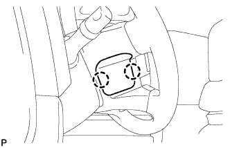 |
Using a screwdriver, remove the steering wheel cover.
| 4. REMOVE STEERING PAD |
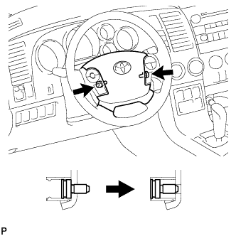 |
Using a T30 "TORX" socket wrench, loosen the 2 screws until the groove along the screw circumference catches on the screw case.
Pull the steering pad toward you.
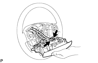 |
Using a thin-bladed screwdriver, release the locking button.
Using a thin-bladed screwdriver, disconnect the 2 connectors.
Detach the horn terminal.
| 5. REMOVE STEERING WHEEL ASSEMBLY |
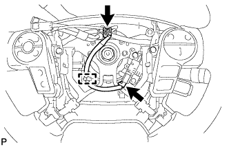 |
Detach the cruise control main wire harness clamp from the steering wheel side.
Disconnect the steering pad switch connector and cruise control main switch connector from the spiral cable.
Remove the steering wheel set nut.
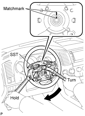 |
Put matchmarks on the steering wheel and main shaft.
Using SST, remove the steering wheel.
| 6. REMOVE LOWER STEERING COLUMN COVER |
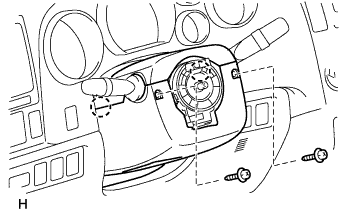 |
Remove the 2 screws.
Detach the 2 claws to remove the lower steering column cover.
| 7. REMOVE UPPER STEERING COLUMN COVER |
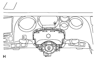 |
Detach the 4 clips.
Detach the claw to remove the upper steering column cover.
| 8. REMOVE TURN SIGNAL SWITCH ASSEMBLY WITH SPIRAL CABLE SUB-ASSEMBLY |
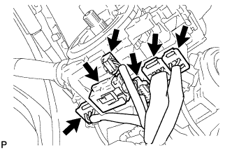 |
Disconnect the all connectors from the turn signal switch with spiral cable.
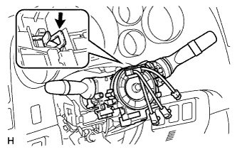 |
Using pliers, grip the claws of the clamp and remove the turn signal switch with spiral cable from the steering column.
| 9. REMOVE FRONT DOOR SCUFF PLATE LH |
| 10. REMOVE COWL SIDE TRIM BOARD LH |
| 11. SEPARATE FRONT DOOR OPENING TRIM WEATHERSTRIP LH |
Separate the front door opening trim weatherstrip LH.
| 12. REMOVE FRONT PILLAR GARNISH LH |
| 13. REMOVE INSTRUMENT SIDE PANEL LH |
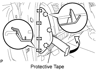 |
Apply protective tape, as shown in the illustration.
Using a moulding remover, disengage the 3 claws and 4 guides and remove the side panel.
| 14. REMOVE HOOD LOCK CONTROL LEVER SUB-ASSEMBLY |
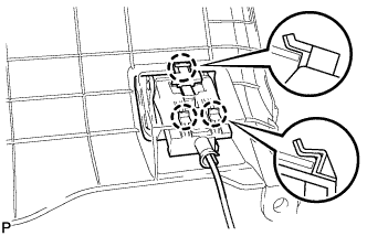 |
Disengage the 3 claws.
Disconnect the hood lock control cable and remove the hood lock control lever sub-assembly.
| 15. REMOVE LOWER INSTRUMENT PANEL FINISH PANEL SUB-ASSEMBLY LH |
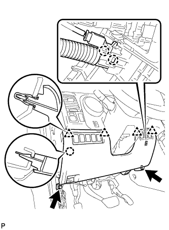 |
Remove the 2 <A> bolts.
Disengage the 4 clips and claw.
Disengage the 2 claws and separate the sensor.
Disconnect the connectors and remove the finish panel.
| 16. REMOVE SHIFT LEVER KNOB SUB-ASSEMBLY |
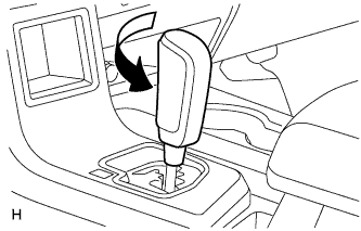 |
Twist the shift lever knob in the direction indicated by the arrow and remove it.
| 17. REMOVE UPPER CONSOLE PANEL SUB-ASSEMBLY |
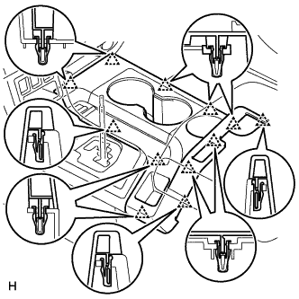 |
Disengage the 12 clips and remove the console panel.
| 18. REMOVE REAR CONSOLE BOX POCKET |
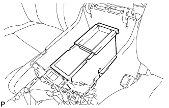 |
Remove the rear console box pocket.
| 19. REMOVE REAR UPPER CONSOLE PANEL SUB-ASSEMBLY |
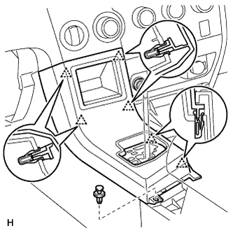 |
Move the shift lever to N.
Remove the clip.
Disengage the 6 clips and remove the console panel.
Disconnect the connector
| 20. REMOVE CONSOLE BOX CARPET |
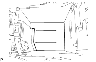 |
Remove the console box carpet.
| 21. REMOVE REAR CONSOLE BOX ASSEMBLY |
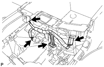 |
Disconnect the connectors.
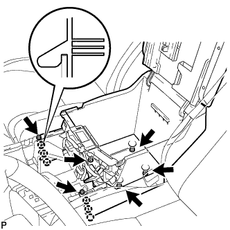 |
Remove the 4 bolts and 2 screws.
Disengage the 6 claws and remove the rear console box.
| 22. REMOVE FRONT CONSOLE BOX |
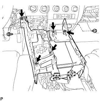 |
Disengage the 2 clamps.
Remove the 2 clips.
Remove the 5 screws and the front console box.
| 23. REMOVE INSTRUMENT CLUSTER FINISH PANEL ASSEMBLY |
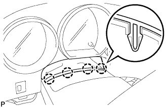 |
Disengage the 4 claws and separate the instrument panel finish panel retainer.
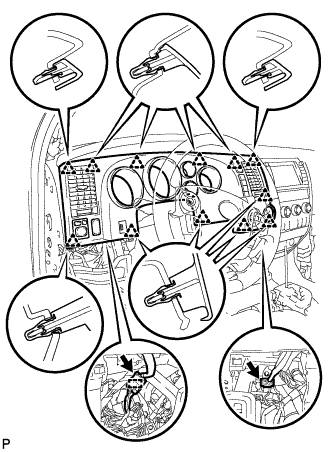 |
Disconnect the 2 connectors and clamp.
Disengage the 12 clips and remove the finish panel.
| 24. REMOVE COMBINATION METER ASSEMBLY |
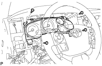 |
Remove the 4 screws.
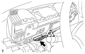 |
Disconnect the connector and disengage the clip and remove the combination meter assembly.
| 25. REMOVE CENTER LOWER INSTRUMENT PANEL FINISH PANEL |
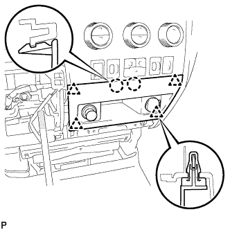 |
Disengage the 4 clips and 2 claws.
Disconnect the connectors and remove the finish panel.
| 26. REMOVE INTEGRATION CONTROL AND PANEL ASSEMBLY |
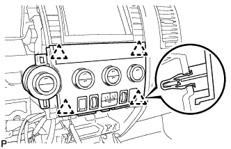 |
Disengage the 4 clips and separate the panel.
Disconnect the connectors and remove the panel.
| 27. REMOVE RADIO RECEIVER ASSEMBLY WITH BRACKET (w/ Radio Receiver) |
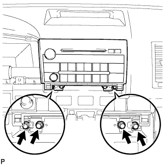 |
Remove the 4 bolts.
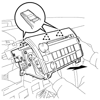 |
Pull the radio receiver to disengage the 3 clips on the backside of the radio receiver.
Disconnect the connectors and remove the radio receiver.
| 28. REMOVE NAVIGATION RECEIVER ASSEMBLY WITH BRACKET (w/ Navigation System) |
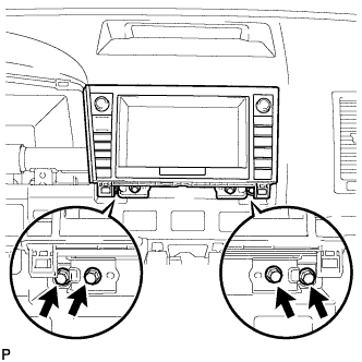 |
Remove the 4 bolts.
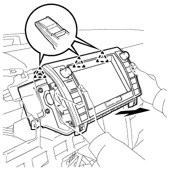 |
Pull the navigation receiver as shown in the illustration to disengage the 3 clips on the backside of the navigation receiver.
Disconnect the connectors and remove the navigation receiver.
| 29. REMOVE INSTRUMENT SIDE PANEL RH |
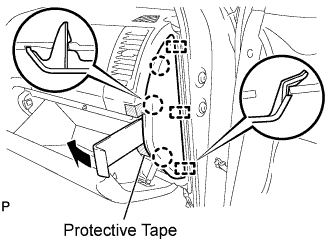 |
Apply protective tape, as shown in the illustration.
Using a moulding remover, disengage the 3 claws and 3 guides and remove the side panel.
| 30. REMOVE FRONT DOOR SCUFF PLATE RH |
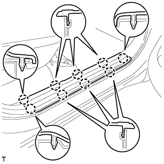 |
Detach the 9 claws and remove the scuff plate.
| 31. REMOVE COWL SIDE TRIM BOARD RH |
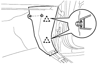 |
Remove the clip.
Disengage the 2 clips and remove the cowl side trim board.
| 32. SEPARATE FRONT DOOR OPENING TRIM WEATHERSTRIP RH |
Separate the front door opening trim weatherstrip RH.
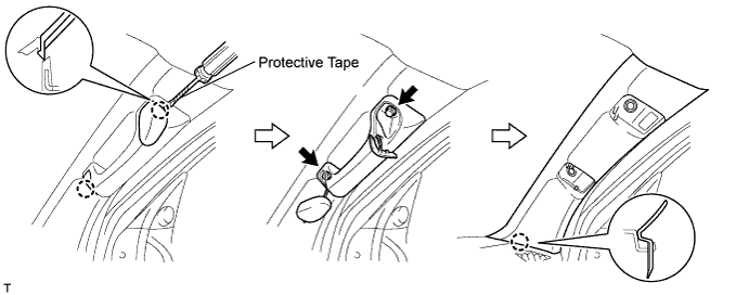
| 33. REMOVE FRONT PILLAR GARNISH RH |
Using a screwdriver with its tip wrapped in protective tape, disengage the 2 claws and remove the 2 assist grip plugs.
Remove the 2 bolts and assist grip.
Detach the claw and remove the front pillar garnish.
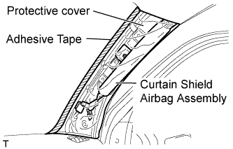 |
Protect the curtain shield airbag.
Thoroughly cover the airbag with a cloth or nylon sheet and fix the ends of the cover with adhesive tape, as shown in the illustration.
| 34. REMOVE NO. 2 INSTRUMENT PANEL UNDER COVER SUB-ASSEMBLY |
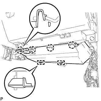 |
Disengage the 4 claws and 2 guides and remove the under cover.
| 35. REMOVE LOWER INSTRUMENT PANEL FINISH PANEL SUB-ASSEMBLY RH |
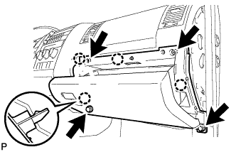 |
Remove the bolt <A> and 3 <D> screws.
Disengage the 4 claws and remove the finish panel.
| 36. REMOVE NO. 2 INSTRUMENT PANEL BOX DOOR SUB-ASSEMBLY |
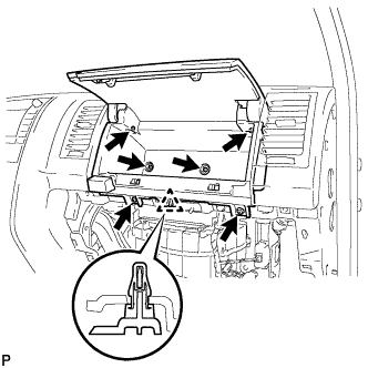 |
Remove the 6 <B> screws.
Disengage the clip and remove the box door.
| 37. REMOVE INSTRUMENT PANEL SPEAKER PANEL SUB-ASSEMBLY |
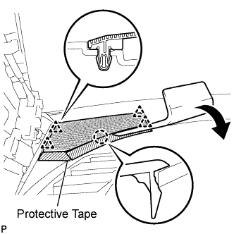 |
Using a moulding remover, disengage the 4 clips and claw, and remove the speaker panel.
| 38. REMOVE FRONT NO. 2 SPEAKER ASSEMBLY LH |
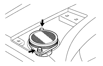 |
Remove the 2 bolts.
Remove the speaker and disconnect the connector.
| 39. REMOVE NO. 2 INSTRUMENT PANEL SPEAKER PANEL SUB-ASSEMBLY |
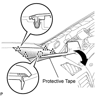 |
Using a moulding remover, disengage the 4 clips, claw, and remove the speaker panel.
| 40. REMOVE FRONT NO. 2 SPEAKER ASSEMBLY RH |
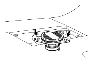 |
Remove the 2 bolts.
Remove the speaker and disconnect the connector.
| 41. REMOVE NO. 3 INSTRUMENT PANEL SPEAKER PANEL SUB-ASSEMBLY |
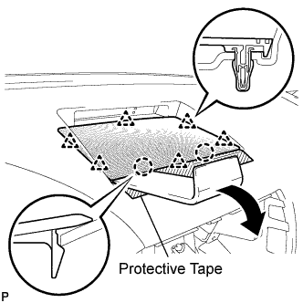 |
Using a moulding remover, disengage the 6 clips, 2 claws, and remove the speaker panel.
| 42. REMOVE FRONT NO. 4 SPEAKER ASSEMBLY (for 14 Speakers) |
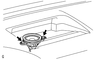 |
Remove the 2 bolts.
Remove the speaker and disconnect the connector.
| 43. REMOVE NO. 1 INSTRUMENT PANEL SAFETY PAD INSERT |
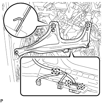 |
Remove the 4 <A> bolts.
Disengage the 2 claws.
Disconnect the connector and clamp and remove the safety pad insert.
| 44. REMOVE INSTRUMENT PANEL SUB-ASSEMBLY (for 14 Speakers) |
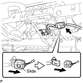 |
Slide the slider and disconnect the airbag connector.
Disengage the clamps and disconnect the connectors.
Remove the bolt and separate the wire harness.
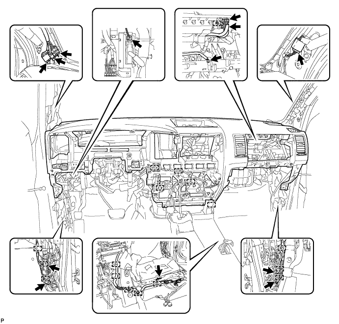
Remove the 2 <F> passenger airbag bolts.
Remove the 3 <C> bolts and 2 <E> nuts.
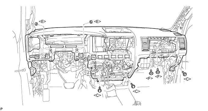
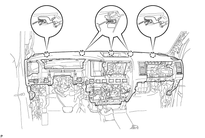
Disengage the 5 claws and remove the instrument panel.
| 45. REMOVE INSTRUMENT PANEL SUB-ASSEMBLY (for 8 Speakers) |
|
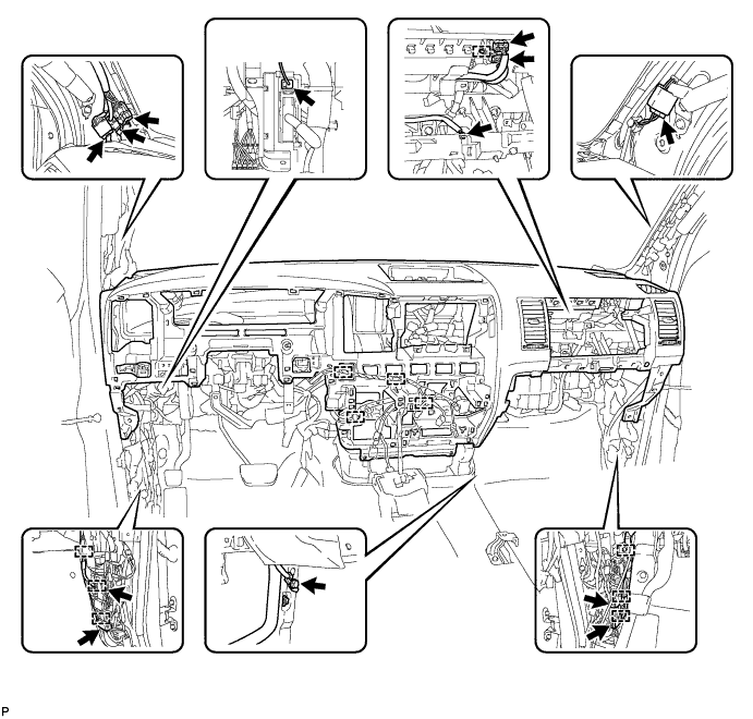
Slide the slider and disconnect the airbag connector.
Disengage the clamps and disconnect the connectors.
Remove the bolt and separate the wire harness.
Remove the 2 <F> passenger airbag bolts.
Remove the 3 <C> bolts and 2 <E> nuts.
Disengage the 5 claws and remove the instrument panel.
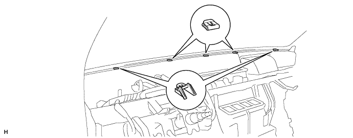
| 46. REMOVE NO. 3 INSTRUMENT PANEL STAY |
Disengage the 5 claws and remove the 5 stays.
| 47. REMOVE GLOVE BOX LIGHT ASSEMBLY |
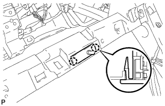 |
Disengage the 2 claws and remove the glove box light.
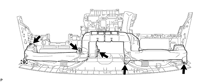
| 48. REMOVE NO. 1 HEATER TO REGISTER DUCT |
Disengage the clamp.
Remove the 5 screws and duct.
| 49. REMOVE NO. 1 SIDE DEFROSTER NOZZLE DUCT |
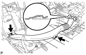 |
Remove the 2 screws.
Disengage the 2 claws and remove the duct.
| 50. REMOVE NO. 2 SIDE DEFROSTER NOZZLE DUCT |
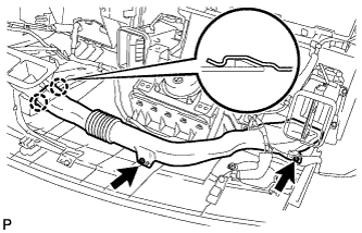 |
Remove the 2 screws.
Disengage the 2 claws and remove the duct.
| 51. REMOVE DEFROSTER NOZZLE ASSEMBLY |
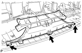 |
Remove the 3 screws and the defroster nozzle.
| 52. REMOVE NO. 3 INSTRUMENT PANEL REGISTER ASSEMBLY |
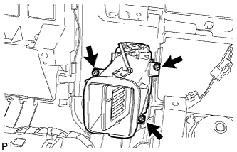 |
Remove the 3 screws and the register.
| 53. REMOVE ACCESSORY METER ASSEMBLY |
Disconnect the connector.
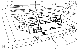 |
Remove the 3 screws and remove the accessory meter assembly.