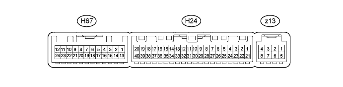
WINDOW DEFOGGER SYSTEM > TERMINALS OF ECU |
| CHECK AIR CONDITIONING AMPLIFIER |
Disconnect the H24 air conditioning amplifier connector.
Measure the resistance and voltage according to the value(s) in the table below.
| Terminal No. (Symbol) | Wiring Color | Terminal Description | Condition | Specified Condition |
| H24-1 (IG+) - H24-14 (GND) | P - W-B | Ignition power supply | Ignition switch ON | 11 to 14 V |
| Ignition switch off | Below 1 V | |||
| H24-21 (B) - H24-14 (GND) | R - W-B | Battery power source | Always | 11 to 14 V |
| H24-14 (GND) - Body ground | W-B - Body ground | Ground | Always | Below 1 Ω |
Reconnect the H24 air conditioning amplifier connector.
Measure the voltage according to the value(s) in the table below.
| Terminal No. (Symbol) | Wiring Color | Terminal Description | Condition | Specified Condition |
| H24-11 (CANH) - H24-14 (GND) | B - W-B | Hi-level CAN bus line | Ignition switch ON | Pulse generation (see waveform 1) |
| H24-12 (CANL) - H24-14 (GND) | W - W-B | Lo-level CAN bus line | Ignition switch ON | Pulse generation (see waveform 2) |
| H24-37 (LIN1) - H24-14 (GND) | SB - W-B | LIN communication signal | Ignition switch ON | Pulse generation |
| H24-38 (RDEF) - H24-14 (GND) | R - W-B | Defogger relay | Ignition switch ON Defogger switch OFF | 11 to 14 V |
| Ignition switch ON Back door window closed Defogger switch ON | Below 1 V |
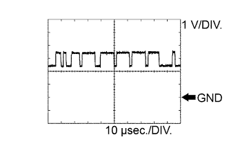 |
Waveform 1 (Reference) : Using an oscilloscope
| Terminal Name | CANH - GND |
| Tester Range | 1 V/DIV., 10 μsec./DIV. |
| Condition | Ignition switch ON |
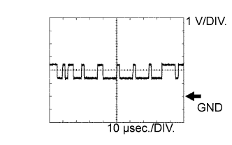 |
Waveform 2 (Reference) : Using an oscilloscope
| Terminal Name | CANL - GND |
| Tester Range | 1 V/DIV., 10 μsec./DIV. |
| Condition | Ignition switch ON |
| CHECK INTEGRATION CONTROL AND PANEL |

Disconnect the H45 integration control and panel connector.
Measure the resistance and voltage according to the value(s) in the table below.
| Terminal No. (Symbol) | Wiring Color | Terminal Description | Condition | Specified Condition |
| H45-16 (IG+) - H45-1 (GND) | P - W-B | Ignition power supply | Ignition switch off | Below 1 V |
| Ignition switch ON | 11 to 14 V | |||
| H45-1 (GND) - Body ground | W-B - Body ground | Ground | Always | Below 1 Ω |
Reconnect the H45 integration control and panel connector.
Measure the voltage according to the value(s) in the table below.
| Terminal No. (Symbol) | Wiring Color | Terminal Description | Condition | Specified Condition |
| H45-3 (STX) - H45-1 (GND) | SB - W-B | LIN communication circuit | Ignition switch ON | Pulse generation |