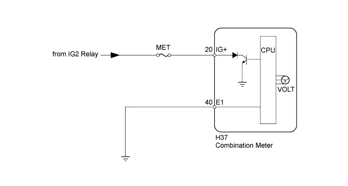
METER / GAUGE SYSTEM > Voltage Meter Malfunction |
| 1.INSPECT FUSE (MET) |
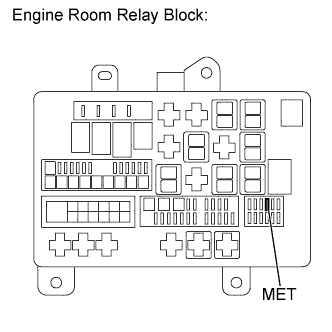 |
Remove the MET fuse from the engine room relay block.
Measure the resistance according to the value(s) in the table below.
| Tester Connection | Condition | Specified Condition |
| MET fuse | Always | Below 1 Ω |
|
| ||||
| OK | |
 |
| 2.PERFORM ACTIVE TEST USING TECHSTREAM (VOLTMETER) |
Connect the Techstream to the DLC3.
Turn the ignition switch to ON.
Turn the Techstream ON.
Enter the following menus: Body Electrical / Combination Meter / Active Test.
According to the display on the Techstream, perform the Active Test.
| Tester Display | Test Part | Control Range | Diagnostic Note |
| Volt Meter Operation | Voltmeter | 0, 3, 6, 9, 12, 15 or 18 | Perform the test with the vehicle stopped and engine idling |
|
| ||||
| OK | |
|
| 3.CHECK HARNESS AND CONNECTOR (COMBINATION METER - BATTERY AND BODY GROUND) |
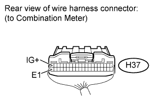 |
Disconnect the H37 meter connector.
Measure the resistance and voltage according to the value(s) in the table below.
| Tester Connection | Condition | Specified Condition |
| H37-40 (E1) - Body ground | Always | Below 1 Ω |
| Tester Connection | Switch Condition | Specified Condition |
| H37-20 (IG+) - Body ground | Ignition switch ON | 11 to 14 V |
| Ignition switch off | Below 1 V |
|
| ||||
| OK | ||
 | ||
| ||
