 |
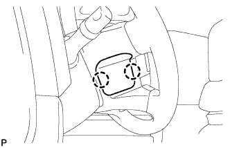
Using a screwdriver, remove the steering wheel cover.
- HINT:
- Tape the screwdriver tip before use.
STEERING COLUMN ASSEMBLY (for Power Tilt and Power Telescopic Steering Column) > REMOVAL |
| 1. PLACE FRONT WHEELS FACING STRAIGHT AHEAD |
| 2. CUSTOMIZE INFORMATION |
Connect the Techstream to the DLC3.
Turn the ignition switch to ON.
Turn the Techstream on.
Enter the following menus: Utility / Customize Setting / Tilt & Telesco.
Turn the auto away/return function OFF.
Turn the ignition switch to ACC.
Operate the tilt and telescopic switch to fully raise the tilt and extend the steering wheel.
Turn the ignition switch OFF.
| 3. DISCONNECT CABLE FROM NEGATIVE BATTERY TERMINAL |
| 4. REMOVE LOWER NO. 3 STEERING WHEEL COVER |
|
Using a screwdriver, remove the steering wheel cover.
| 5. REMOVE LOWER NO. 2 STEERING WHEEL COVER |
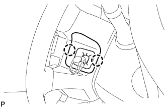 |
Using a screwdriver, remove the No. 2 steering wheel cover.
| 6. REMOVE STEERING PAD |
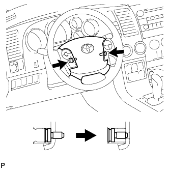 |
Using a T30 "TORX" socket wrench, loosen the 2 screws until the groove along the screw circumference catches on the screw case.
Pull the steering pad toward you.
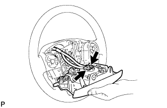 |
Using a thin-bladed screwdriver, release the locking button.
Using a thin-bladed screwdriver, disconnect the 2 connectors.
Detach the horn terminal.
| 7. REMOVE STEERING WHEEL ASSEMBLY |
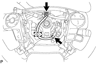 |
Detach the cruise control main wire harness clamp from the steering wheel side.
Disconnect the steering pad switch connector and cruise control main switch connector from the spiral cable.
Remove the steering wheel set nut.
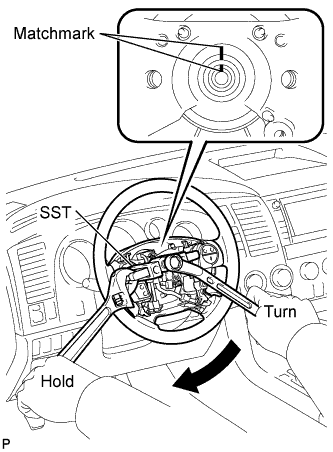 |
Put matchmarks on the steering wheel and main shaft.
Using SST, remove the steering wheel.
| 8. REMOVE LOWER STEERING COLUMN COVER |
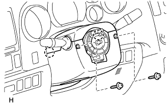 |
Remove the 2 screws.
Detach the 2 claws to remove the lower steering column cover.
| 9. REMOVE UPPER STEERING COLUMN COVER |
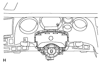 |
Detach the 4 clips.
Detach the claw to remove the upper steering column cover.
| 10. REMOVE COMBINATION SWITCH |
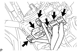 |
Disconnect the all connectors from the turn signal switch with spiral cable.
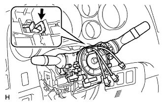 |
Using pliers, grip the claws of the clamp and remove the turn signal switch with spiral cable from the steering column.
| 11. REMOVE FRONT DOOR SCUFF PLATE LH |
| 12. REMOVE COWL SIDE TRIM BOARD LH |
| 13. REMOVE INSTRUMENT SIDE PANEL LH |
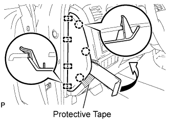 |
Apply protective tape, as shown in the illustration.
Using a moulding remover, disengage the 3 claws and 4 guides and remove the side panel.
| 14. REMOVE LOWER INSTRUMENT PANEL FINISH PANEL SUB-ASSEMBLY LH |
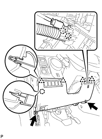 |
Remove the 2 <A> bolts.
Disengage the 4 clips and claw.
Disengage the 2 claws and separate the sensor.
Disconnect the connectors and remove the finish panel.
| 15. REMOVE NO. 1 INSTRUMENT PANEL SAFETY PAD INSERT |
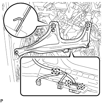 |
Remove the 4 <A> bolts.
Disengage the 2 claws.
Disconnect the connector and clamp and remove the safety pad insert.
| 16. REMOVE NO. 3 AIR DUCT SUB-ASSEMBLY |
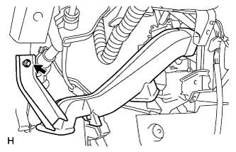 |
Remove the bolt and air duct.
| 17. REMOVE STEERING INTERMEDIATE SHAFT ASSEMBLY |
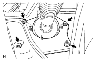 |
Remove the 3 bolts and nut.
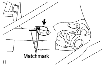 |
Put matchmarks on the steering intermediate shaft and the steering column.
Remove the bolt and steering intermediate shaft from the steering column.
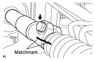 |
Put matchmarks on the No. 2 steering intermediate shaft and steering intermediate shaft.
Remove the bolt.
Separate the steering intermediate shaft from the No. 2 steering intermediate shaft.
| 18. REMOVE NO. 2 STEERING INTERMEDIATE SHAFT SUB-ASSEMBLY |
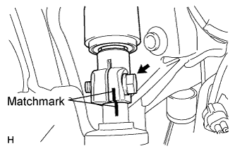 |
Put matchmarks on the No. 2 steering intermediate shaft and power steering gear.
Remove the bolt and No. 2 steering intermediate shaft from the power steering gear.
| 19. REMOVE STEERING COLUMN ASSEMBLY |
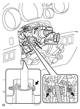 |
Disconnect the connectors and disengage the wire.
Remove the bolt and 2 nuts. Then remove the steering column from the instrument panel reinforcement.