Home › Vehicle Interior › METER / GAUGE / DISPLAY › DRIVE MONITOR SWITCH

DRIVE MONITOR SWITCH > INSPECTION

for Preparation Click here


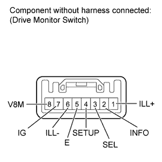
1. INSPECT DRIVE MONITOR SWITCH


    E146528E02
  1. Measure the resistance according to the value(s) in the table below.

    Standard Resistance:
    Tester Connection
    Switch Condition
    Specified Condition
    2 (INFO) - 5 (E)
    Info switch off
    10 kΩ or higher
    Info switch on
    Below 1 Ω
    3 (SEL) - 5 (E)
    Select reset switch off
    10 kΩ or higher
    Select reset switch on
    Below 1 Ω
    4 (SETUP) - 5 (E)
    Setup us/m switch off
    10 kΩ or higher
    Setup us/m switch on
    Below 1 Ω
    7 (IG) - 8 (V8M)
    Sonar switch off
    10 kΩ or higher
    Sonar switch on
    Below 1 Ω

    If the result is not as specified, replace the monitor switch.

  1. Inspect the switch illumination.

    1. Connect the positive (+) lead from the battery to terminal 1 (ILL+) and the negative (-) lead to terminal 6 (ILL-), and then check the Drive Monitor Switch.

      OK:
      Switch illuminate.