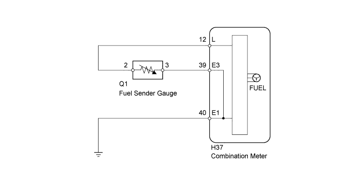
METER / GAUGE SYSTEM > Fuel Receiver Gauge Malfunction |
| 1.CHECK DTC |
Check the DTCs (Click here).
| Result | Proceed to |
| DTC B1500 is not output | A |
| DTC B1500 is output | B |
|
| ||||
| A | |
 |
| 2.PERFORM ACTIVE TEST USING TECHSTREAM (FUEL RECEIVER GAUGE) |
Connect the Techstream to the DLC3.
Turn the ignition switch to ON.
Turn the Techstream ON.
Enter the following menus: Body Electrical / Combination Meter / Active Test.
According to the display on the Techstream, perform the Active Test.
| Tester Display | Test Part | Control Range | Diagnostic Note |
| Fuel Meter Operation | Fuel receiver gauge | EMPTY, 1/2 or FULL | - |
|
| ||||
| OK | ||
 | ||
| ||
