ENGINE UNIT > REMOVAL |
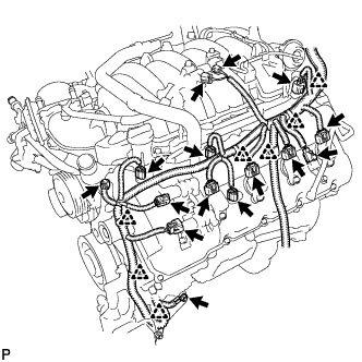
| 1. REMOVE ENGINE WIRE |
|
Disconnect the 2 camshaft timing control valve connectors.
Disconnect the 4 ignition coil connectors.
Disconnect the 2 VVT sensor connectors.
Disconnect the camshaft position sensor connector.
Disconnect the vacuum switching valve connector (for ACIS).
Disconnect the purge VSV connector.
Disconnect the engine coolant temperature sensor connector.
Disconnect the fuel injector connector.
Disconnect the noise filter connector.
Remove the bolt and disconnect the 7 clamps.
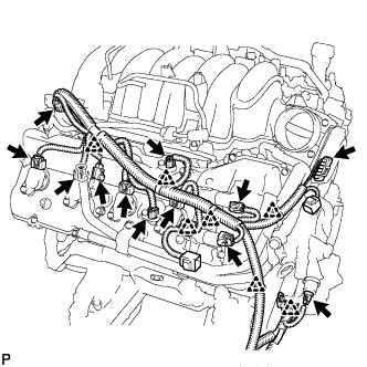 |
Disconnect the 2 camshaft timing control valve connectors.
Disconnect the 4 ignition coil connectors.
Disconnect the 2 VVT sensor connectors.
Disconnect the fuel injector connector.
Disconnect the noise filter connector.
Disconnect the throttle sensor connector.
Disconnect the oil pressure sender gauge connector.
Disconnect the 7 clamps.
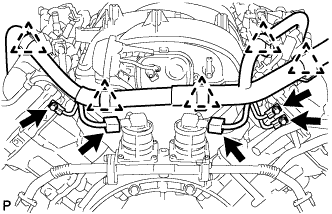 |
Disconnect the 2 air switching valve connectors.
Disconnect the 5 clamps.
Remove the 3 bolts.
Remove the engine wire.
| 2. REMOVE NO. 1 FUEL PIPE SUB-ASSEMBLY |
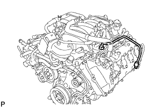 |
Remove the No. 1 fuel pipe (Click here).
| 3. REMOVE CYLINDER BLOCK WATER DRAIN COCK PLUG |
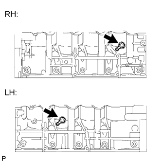 |
Remove the 2 water drain cock plugs from the water drain cocks.
Remove the 2 water drain cocks from the cylinder block.
| 4. REMOVE FRONT ENGINE MOUNTING INSULATOR |
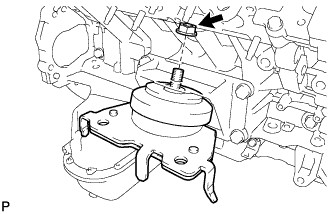 |
Remove the nut and mounting insulator.
| 5. REMOVE FRONT ENGINE MOUNTING INSULATOR LH |
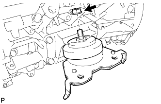 |
Remove the nut and mounting insulator.
| 6. REMOVE FRONT NO. 1 ENGINE MOUNTING BRACKET RH |
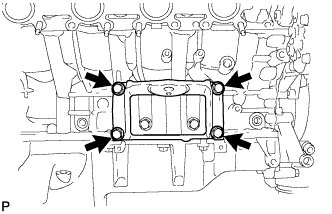 |
Remove the 4 bolts and mounting bracket.
| 7. REMOVE FRONT NO. 1 ENGINE MOUNTING BRACKET LH |
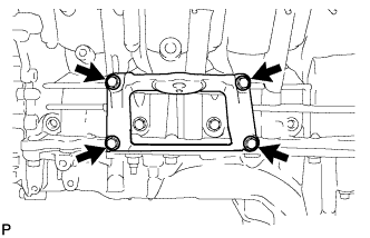 |
Remove the 4 bolts and mounting bracket.
| 8. REMOVE NO. 1 ENGINE COVER SUB-ASSEMBLY |
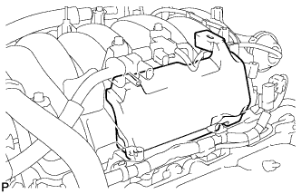 |
Remove the No. 1 engine cover sub-assembly.
| 9. REMOVE NO. 3 ENGINE COVER |
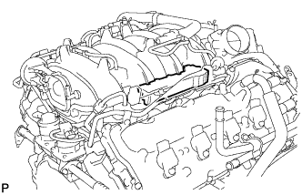 |
Remove the No. 3 engine cover.
| 10. DISCONNECT NO. 2 FUEL TUBE SUB-ASSEMBLY |
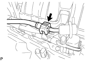 |
Disconnect the No. 2 fuel tube from the fuel pressure regulator (Click here).
| 11. DISCONNECT FUEL TUBE SUB-ASSEMBLY |
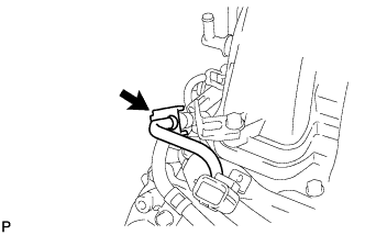 |
Disconnect the fuel tube from the fuel delivery pipe (Click here).
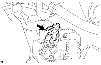 |
Disconnect the fuel tube from the No. 2 fuel delivery pipe (Click here).
| 12. REMOVE FUEL DELIVERY PIPE SUB-ASSEMBLY |
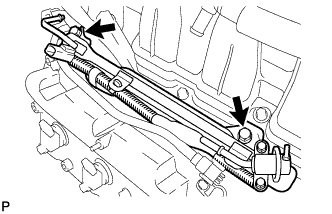 |
Remove the 2 bolts and fuel delivery pipe.
Remove the 2 spacers and 4 insulators from the intake manifold.
| 13. REMOVE NO. 2 FUEL DELIVERY PIPE SUB-ASSEMBLY |
Disconnect the No. 7 wire harness connector.
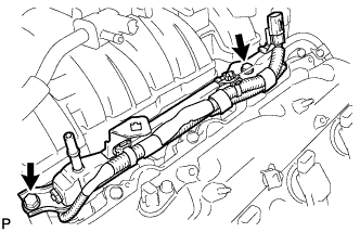 |
Remove the 2 bolts and No. 2 fuel delivery pipe.
Remove the 2 spacers and 4 insulators from the intake manifold.
| 14. REMOVE VENTILATION HOSE ASSEMBLY |
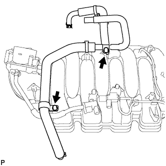 |
Remove the 2 bolts and ventilation hose from the intake manifold.
| 15. REMOVE NO. 1 HOSE TO HOSE TUBE |
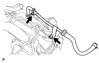 |
Remove the 2 bolts and No. 1 tube.
| 16. REMOVE INTAKE MANIFOLD |
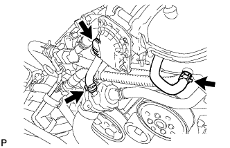 |
Disconnect the 2 water by-pass hoses.
Disconnect the throttle W/ motor body connector.
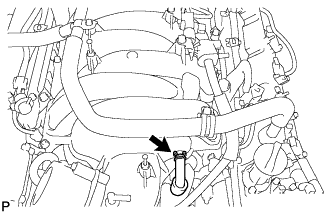 |
Disconnect the ventilation hose.
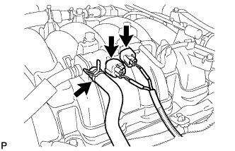 |
Disconnect the vacuum switching valve connector.
Disconnect the purge line hose from the No. 1 vacuum switching valve assembly.
Disconnect the vacuum switching valve connector (for ACIS).
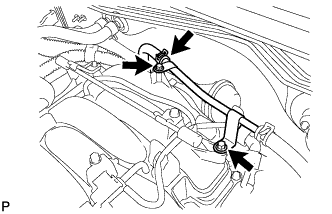 |
Remove the 2 bolts.
Disconnect the No. 1 tube from the union to connector tube hose, and move the hose aside.
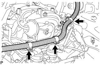 |
Disconnect the 3 wire clamps from the 3 wire harness clamp brackets.
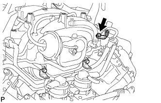 |
Remove the bolt and wire harness clamp bracket from the intake manifold.
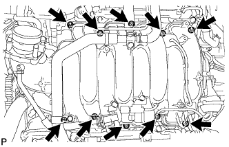 |
Remove the 2 nuts, 8 bolts, intake manifold and 2 gaskets.
| 17. REMOVE NO. 2 FUEL TUBE SUB-ASSEMBLY |
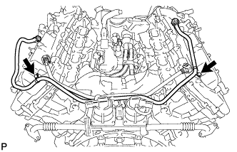 |
Remove the 2 bolts and No. 2 fuel tube.
| 18. REMOVE FUEL TUBE SUB-ASSEMBLY |
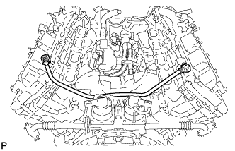 |
Remove the fuel tube.
| 19. REMOVE WATER BY-PASS PIPE HOSE (w/ Oil Cooler) |
Remove the 3 bolts.
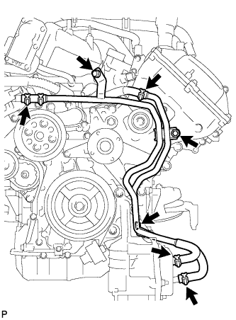 |
Disconnect the 4 hoses and remove the water by-pass pipe.
| 20. REMOVE NO. 1 WATER BY-PASS HOSE |
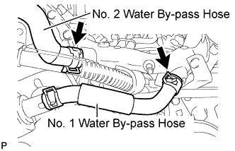 |
Disconnect the No. 1 water by-pass hose from the water by-pass joint and water inlet housing.
| 21. REMOVE FRONT WATER BY-PASS JOINT |
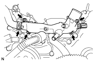 |
Disconnect the No. 2 water by-pass hose from the water by-pass joint.
Remove the 4 nuts, water by-pass joint and 2 gaskets.
| 22. REMOVE NO. 2 CYLINDER HEAD COVER |
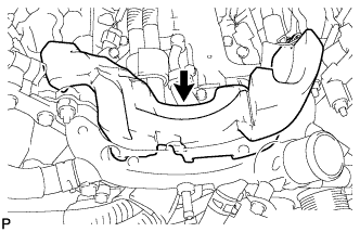 |
Remove the No. 2 cylinder head cover.
| 23. REMOVE NO. 1 ENGINE COVER |
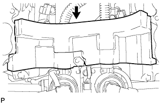 |
Remove the No. 1 engine cover.
| 24. SEPARATE AIR PIPE SUB-ASSEMBLY |
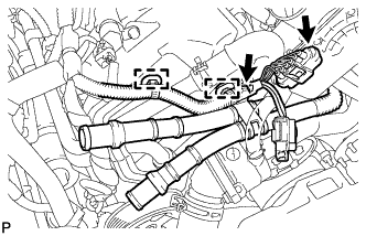 |
Disconnect the connector and separate the 2 clamps and wire harness.
Remove bolt and separate the air pipe.
| 25. REMOVE WATER BY-PASS PIPE SUB-ASSEMBLY |
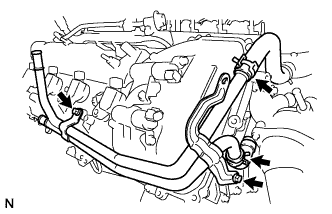 |
Disconnect the 2 hoses.
Remove the 2 bolts and water by-pass pipe.
| 26. REMOVE WATER PUMP PULLEY |
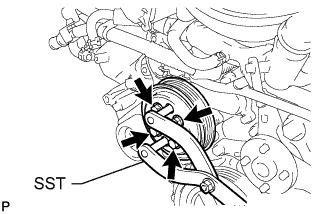 |
Using SST, hold the water pump pulley.
Remove the 4 bolts and water pump pulley.
| 27. REMOVE NO. 1 IDLER PULLEY SUB-ASSEMBLY |
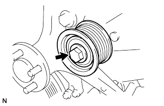 |
Remove the bolt and idler pulley.
| 28. REMOVE FLUID COUPLING BRACKET |
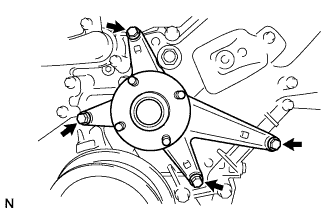 |
Remove the 4 bolts and fluid coupling bracket.
| 29. REMOVE V-RIBBED BELT TENSIONER ASSEMBLY |
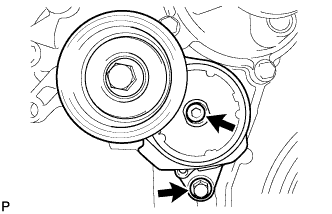 |
Remove the standard bolt, 6 mm hexagon wrench bolt and belt tensioner.
| 30. REMOVE OIL PRESSURE SENDER GAUGE ASSEMBLY |
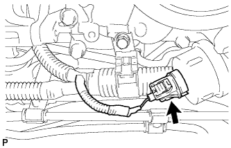 |
Disconnect the sender gauge connector.
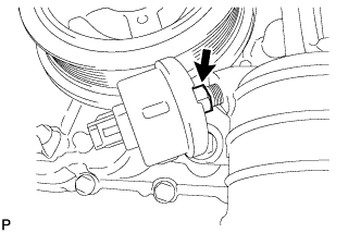 |
Remove the oil pressure sender gauge.
| 31. REMOVE AIR PIPE SUB-ASSEMBLY |
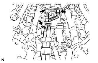 |
Remove the bolt, disconnect the 2 hoses, and remove the air pipe.
| 32. REMOVE INLET WATER HOUSING |
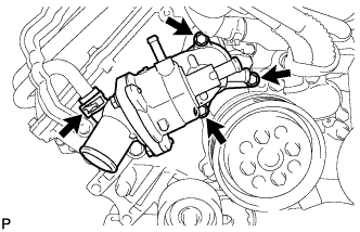 |
Remove the 3 bolts and inlet water housing and disconnect the No. 3 water by-pass hose from the inlet water housing.
Remove the gasket from the water pump.
| 33. REMOVE ELECTRIC AIR CONTROL VALVE ASSEMBLY |
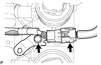 |
Disconnect the knock sensor connector.
Remove the bolt and bracket.
Disconnect the 2 electric air control valve connectors.
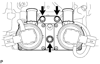 |
Remove the 3 bolts and electric air control valve assembly.
| 34. REMOVE NO. 2 AIR TUBE |
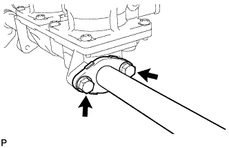 |
Remove the 2 bolts, No. 2 air tube and gasket.
| 35. REMOVE NO. 3 AIR TUBE |
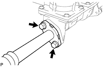 |
Remove the 2 bolts, No. 3 air tube and gasket.
| 36. REMOVE ENGINE WIRE |
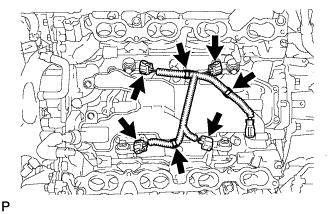 |
Disconnect the 4 knock sensor connectors.
Disconnect the 3 clamps. Then remove the engine wire.
| 37. REMOVE CASE SEPARATOR |
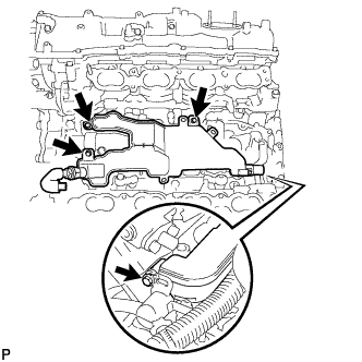 |
Remove the 4 bolts and case separator.
| 38. REMOVE KNOCK SENSOR |
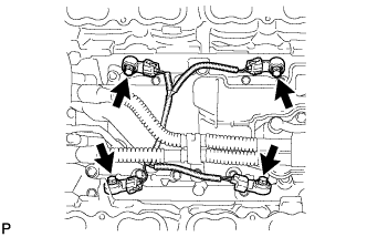 |
Disconnect the 4 knock sensor connectors.
Remove the 4 bolts and 4 knock sensors.
| 39. REMOVE IGNITION COIL ASSEMBLY |
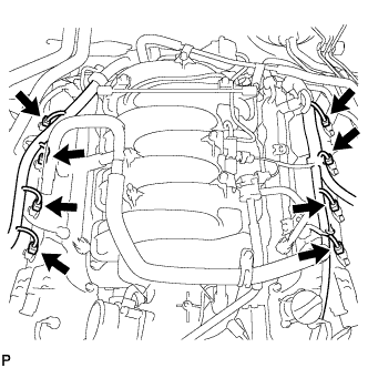 |
Disconnect the 8 ignition coil connectors.
Remove the 8 bolts and 8 ignition coils.
| 40. REMOVE RADIO SETTING CONDENSER |
Remove the 2 bolts and 2 noise filters from the cylinder head cover.