 |
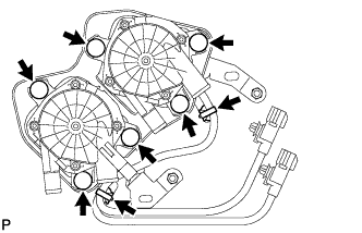
Connect the 6 air pump insulators to the air pump and install the air pump to the bracket.
AIR PUMP > INSTALLATION |
| 1. INSTALL AIR PUMP ASSEMBLY |
|
Connect the 6 air pump insulators to the air pump and install the air pump to the bracket.
Attach the 2 wire harness clamps to the bracket.
| 2. CONNECT NO. 1 AIR INJECTION SYSTEM HOSE |
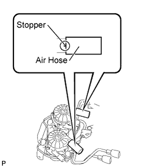 |
Connect the 2 No. 1 air injection system hoses to the air pump.
| 3. INSTALL AIR PUMP INLET |
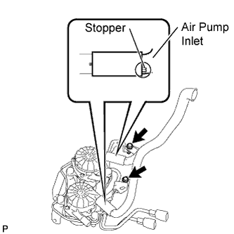 |
Connect the air pump inlet to the 2 No. 1 air injection system hoses.
Install the 2 bolts.
| 4. INSTALL AIR PUMP ASSEMBLY WITH BRACKET |
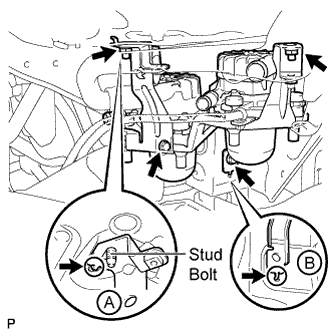 |
Install the air pump to the vehicle.
Insert the bracket tab into the slot and insert the stud bolt into the bracket hole as shown in illustration A. Then slide the bracket.
Insert the bracket tab into the slot shown in illustration B.
Install the 2 bolts and 2 nuts.
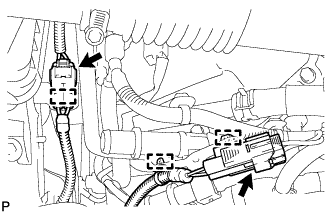 |
Connect the 2 air pump connectors and attach the 3 wire harness claws.
| 5. INSTALL NO. 3 AIR INJECTION SYSTEM HOSE |
Connect the No. 3 air injection system hose so that its paint mark aligns with the air pump's rib as shown in the illustration below labeled A.
Connect the clamp to the No. 3 air injection system hose shown in the illustration below labeled B. Then insert the clamp's clip into the body hole.
Connect the No. 3 air injection system hose to the air tube shown in the illustration below labeled C.
Connect the clamp to the No. 3 air injection system hose and wire harness shown in the illustration below labeled D. Then insert the clamp's clip into the body hole.
| 6. INSTALL NO. 2 AIR INJECTION SYSTEM HOSE |
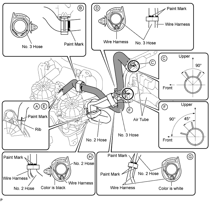
Connect the No. 2 air injection system hose so that its paint mark aligns with the air pump's rib as shown in the illustration below labeled E.
Connect the No. 2 air injection system hose to the air tube shown in the illustration below labeled F.
Connect the white colored clamp to the No. 2 air injection system hose and wire harness shown in the illustration below labeled G.
Connect the black colored clamp to the No. 2 air injection system hose and wire harness shown in the illustration below labeled H. Then insert the clamp's clip into the body hole.
| 7. INSTALL FRONT FENDER APRON SEAL RH |
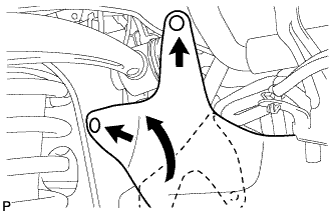 |
Install the fender apron seal with the 2 clips.
| 8. INSTALL FRONT FENDER LINER RH |
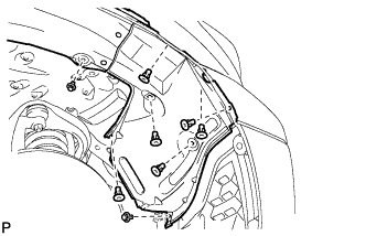 |
Install the fender liner with the 8 clips.