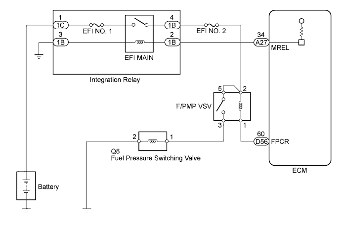
DTC P109C Open in Fuel Pressure Switching Valve Circuit |
DTC P109D Short in Fuel Pressure Switching Valve Circuit |
| DTC No. | DTC Detection Condition | Trouble Area |
| P109C | The fuel pressure switching valve relay circuit is open or shorted to ground. (1 trip detection logic) |
|
| P109D | The fuel pressure switching valve relay circuit is shorted to the power supply. (1 trip detection logic) |
|
| Related DTCs | P109C: F/PMP VSV relay range check (Low voltage) P109D: F/PMP VSV relay range check (High voltage) |
| Required Sensors/Components (Main) | F/PMP VSV relay |
| Required Sensors/Components (Related) | - |
| Frequency of Operation | Continuous |
| Duration | 3 seconds |
| MIL Operation | None |
| Sequence of Operation | None |
| Monitor runs whenever following DTCs not present | None |
| Battery voltage | 8 V or higher |
| Ignition switch | ON |
| Starter | OFF |
| When either condition below is met | Condition 1 or 2 |
| 1. When both conditions below are met | Condition a and b |
| a. Current F/PMP VSV relay | OFF |
| b. Last F/PMP VSV relay | OFF |
| 2. When both conditions below are met | Condition a and b |
| a. Current F/PMP VSV relay | ON |
| b. Last F/PMP VSV relay | ON |
| F/PMP VSV relay output terminal voltage | Low |
| F/PMP VSV relay output terminal voltage | High |
| 1.INSPECT RELAY (F/PMP VSV) |
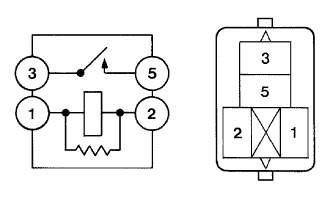 |
Remove the fuel pressure control valve relay (F/PMP VSV) from the engine room relay block.
Measure the resistance according to the value(s) in the table below.
| Tester Connection | Condition | Specified Condition |
| 3 - 5 | When no battery voltage applied to terminals 1 and 2 | 10 kΩ or higher |
| 3 - 5 | When battery voltage applied to terminals 1 and 2 | Below 1 Ω |
|
| ||||
| OK | |
 |
| 2.INSPECT RELAY (POWER SOURCE VOLTAGE) |
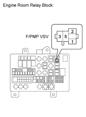 |
Remove the fuel pressure control valve relay (F/PMP VSV) from the engine room relay block.
Turn the ignition switch to ON.
Measure the voltage according to the value(s) in the table below.
| Tester Connection | Switch Condition | Specified Condition |
| F/PMP VSV relay (2) - Body ground | Ignition switch ON | 11 to 14 V |
| F/PMP VSV relay (5) - Body ground | Ignition switch ON | 11 to 14 V |
|
| ||||
| OK | |
|
| 3.CHECK HARNESS AND CONNECTOR (F/PMP VSV RELAY - ECM) |
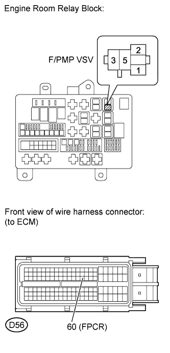 |
Remove the fuel pressure control valve relay (F/PMP VSV) from the engine room relay block.
Disconnect the ECM connector.
Measure the resistance according to the value(s) in the table below.
| Tester Connection | Condition | Specified Condition |
| F/PMP VSV relay (1) - D56-60 (FPCR) | Always | Below 1 Ω |
| F/PMP VSV relay (1) or D56-60 (FPCR) - Body ground | Always | 10 kΩ or higher |
|
| ||||
| OK | ||
 | ||
| ||
| 4.CHECK HARNESS AND CONNECTOR (F/PMP VSV RELAY - EFI MAIN RELAY) |
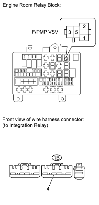 |
Remove the integration relay (EFI MAIN) from the engine room relay block.
Remove the fuel pressure control valve relay (F/PMP VSV) from the engine room relay block.
Measure the resistance according to the value(s) in the table below.
| Tester Connection | Condition | Specified Condition |
| F/PMP VSV relay (2) - 1B-4 | Always | Below 1 Ω |
| F/PMP VSV relay (5) - 1B-4 | Always | Below 1 Ω |
| F/PMP VSV relay (2) or 1B-4 - Body ground | Always | 10 kΩ or more |
| F/PMP VSV relay (5) or 1B-4 - Body ground | Always | 10 kΩ or more |
|
| ||||
| OK | ||
| ||
| ||

