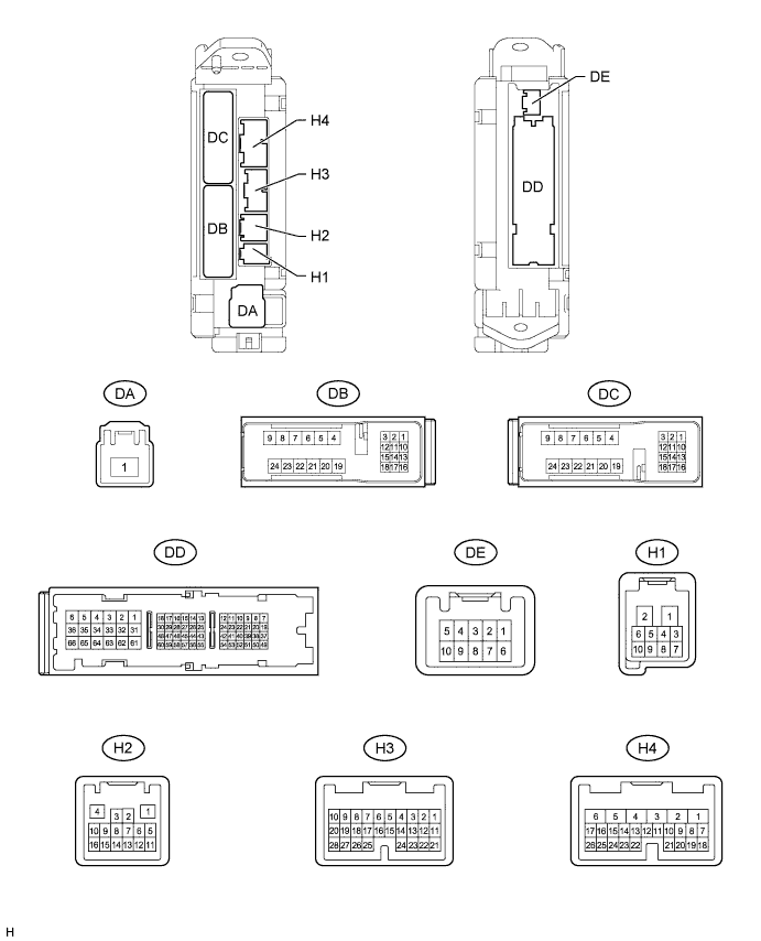
WIPER AND WASHER SYSTEM > TERMINALS OF ECU |
| CHECK MAIN BODY ECU (COWL SIDE JUNCTION BLOCK LH) |
Disconnect the DA, DB and DD main body ECU connectors.
Measure the resistance and voltage according to the value(s) in the table below.
| Terminal No. (Symbol) | Wiring Color | Terminal Description | Condition | Specified Condition |
| DA-1 (ALTB) - Body ground | B - Body ground | Battery power supply | Always | 11 to 14 V |
| DB-13 (BECU) - Body ground | GR - Body ground | Battery power supply | Always | 11 to 14 V |
| DD-62 (GND1, 2) - Body ground | W-B - Body ground | Ground | Always | Below 1 Ω |
Reconnect the main body ECU connectors.
Measure the voltage according to the value(s) in the table below.
| Terminal No. (Symbol) | Wiring Color | Terminal Description | Condition | Specified Condition |
| DD-43 (IG) - DD-62 (GND1, 2) | LG - W-B | IG power supply | Ignition switch off | Below 1 V |
| Ignition switch ON | 11 to 14 V | |||
| H2-10 (LIN2) - DD-62 (GND1, 2) | V - W-B | LIN communication signal | Ignition switch ON | Signal waveform |
| H2-14 (RWMR) - DD-62 (GND1, 2) | BE - W-B | Rear washer motor operation signal | Ignition switch ON and rear washer motor OFF | 11 to 14 V |
| Ignition switch ON and rear washer motor ON | Below 1 V | |||
| H3-2 (RWIN) - DD-62 (GND1, 2) | L - W-B | Rear wiper switch signal | Ignition switch ON and rear wiper switch OFF | 11 to 14 V |
| Ignition switch ON and wiper switch LO | Below 1 V | |||
| H3-9 (RWON) - DD-62 (GND1, 2) | W - W-B | Rear wiper switch signal | Ignition switch ON and rear wiper switch OFF | 11 to 14 V |
| Ignition switch ON and rear wiper switch HI | Below 1 V | |||
| H4-7 (RWSW) - DD-62 (GND1, 2) | Y - W-B | Rear washer switch signal | Ignition switch ON and rear washer switch OFF | 11 to 14 V |
| Ignition switch ON and rear washer switch ON | Below 1 V | |||
| DD-23 (HRLY) - DD-62 (GND1, 2) | SB - W-B | Headlight LO signal | Headlight LO switch OFF | 11 to 14 V |
| Headlight LO switch ON | Below 1 V | |||
| DB-12 (IG) - DD-62 (GND1, 2) | Y - W-B | Headlight cleaner control relay IG signal | Ignition switch off | Below 1 V |
| Ignition switch ON | 11 to 14 V |
| CHECK BACK DOOR ECU |
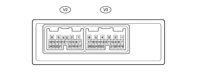
Disconnect the V2 and V3 back door ECU connectors.
Measure the resistance and voltage according to the value(s) in the table below.
| Terminal No. (Symbol) | Wiring Color | Terminal Description | Condition | Specified Condition |
| V2-1 (BDR) - Body ground | SB - Body ground | Battery power supply | Always | 11 to 14 V |
| V2-6 (GND) - Body ground | W-B - Body ground | Ground | Always | Below 1 Ω |
| V2-7 (BECU) - Body ground | GR - Body ground | Battery power supply | Always | 11 to 14 V |
| V2-8 (SIG) - Body ground | Y - Body ground | IG power supply | Ignition switch off | Below 1 V |
| Ignition switch ON | 11 to 14 V | |||
| V3-7 (BKUL) - V3-19 (KEYE) | LG - BE | Tail gate control switch signal | Back door key cylinder turned UNLOCK | Below 1 Ω |
| V3-8 (BKL) - V3-19 (KEYE) | G - BE | Tail gate control switch signal | Back door key cylinder turned LOCK | Below 1 Ω |
Reconnect the back door ECU connectors.
Measure the resistance and voltage according to the value(s) in the table below.
| Terminal No. (Symbol) | Wiring Color | Terminal Description | Condition | Specified Condition |
| V2-16 (MPX1) - V2-6 (GND) | Y - W-B | LIN communication signal | Ignition switch ON | Signal waveform |
| V2-21 (A UP) - V2-6 (GND) | G - W-B | Back door power window AUTO UP signal | Ignition switch ON and back door power window switch OFF → AUTO UP | Pulse generation → Below 1 V |
| V2-22 (BUP) - V2-6 (GND) | BE - W-B | Back door power window UP signal | Ignition switch ON and back door power window switch OFF → UP | Pulse generation → Below 1 V |
| V2-23 (BDN) - V2-6 (GND) | V - W-B | Back door power window DOWN signal | Ignition switch ON and back door power window switch OFF → DOWN | Pulse generation → Below 1 V |
| V2-24 (A DN) - V2-6 (GND) | L - W-B | Back door power window AUTO DOWN signal | Ignition switch ON and back door power window switch OFF → AUTO DOWN | Pulse generation → Below 1 V |
| V3-5 (BDUP) - V2-6 (GND) | BE - W-B | Back door power window UP operation signal | Ignition switch ON and back door power window switch OFF → UP | Below 1 V → 11 to 14 V |
| V3-6 (BDDN) - V2-6 (GND) | P - W-B | Back door power window DOWN operation signal | Ignition switch ON and back door power window switch OFF → DOWN | Below 1 V → 11 to 14 V |
| V3-1 (WIP-) - V2-6 (GND) | P - W-B | Rear wiper motor operation signal | Ignition switch ON and rear wiper switch LO or HI | Pulse generation |
| V3-2 (WIP+) - V2-6 (GND) | L - W-B | Rear wiper motor operation signal | Ignition switch ON and rear wiper switch LO or HI | Pulse generation |
| V3-16 (W) - V2-6 (GND) | R - W-B | Rear wiper reverse position switch signal | Ignition switch ON and rear wiper switch LO or HI | Pulse generation |
| V3-17 (P) - V3-25 (SGND) | V - G | Rear wiper retractable position switch signal | Ignition switch ON and rear wiper switch OFF → ON | Below 1 V → Pulse generation |
| V3-12 (DSV) - V3-23 (DSG) | LG - SB | Power supply for Hall-IC | Ignition switch ON | 11 to 14 V |
| V3-13 (DS1) - V3-23 (DSG) | L - SB | Back door power window glass position signal | Back door power window operation | Pulse generation |
| V3-14 (DS2) - V3-23 (DSG) | Y - SB | Back door power window glass position signal | Back door power window operation | Pulse generation |
| V3-19 (KEYE) - V2-6 (GND) | BE - W-B | Ground for Tail gate control switch | Always | Below 1 Ω |
| V3-23 (DSG) - V2-6 (GND) | SB - W-B | Ground for Hall-IC | Always | Below 1 Ω |
| V3-25 (SGND) - V2-6 (GND) | G - W-B | Ground for rear wiper reverse position and rear wiper retractable position switch | Always | Below 1 Ω |
| CHECK HEADLIGHT CLEANER CONTROL RELAY |
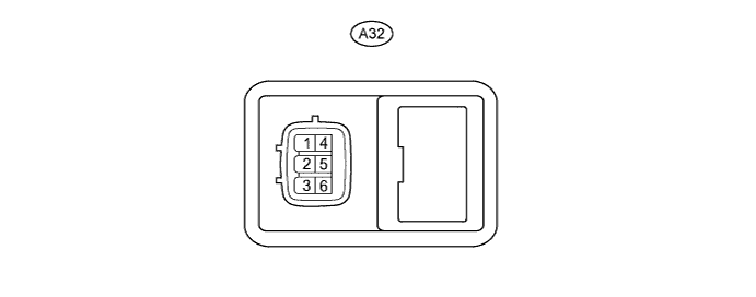
Disconnect the relay connector.
Measure the resistance and voltage according to the value(s) in the table below.
| Terminal No. (Symbol) | Wiring Color | Terminal Description | Condition | Specified Condition |
| A32-3 (IG) - A32-4 (E) | GR - W-B | IG power supply | Ignition switch off | Below 1 V |
| Ignition switch ON | 11 to 14 V | |||
| A32-4(E) - Body ground | W-B - Body ground | Ground | Always | Below 1 Ω |
| A32-2 (H) - A32-4 (E) | BR - W-B | Headlight cleaner switch and headlight switch operation signal | Headlight cleaner switch OFF | Below 1 V |
| Headlight switch OFF | Below 1 V | |||
| Headlight cleaner switch ON and headlight switch ON | 11 to 14 V |
Reconnect the relay connector.
Measure the voltage according to the value(s) in the table below.
| Terminal No. (Symbol) | Wiring Color | Terminal Description | Condition | Specified Condition |
| A32-6 (PB) - A32-4 (E) | R - W-B | Headlight cleaner motor operation signal | Headlight cleaner motor stopped | 11 to 14 V |
| Headlight cleaner motor operating | Below 1 V |