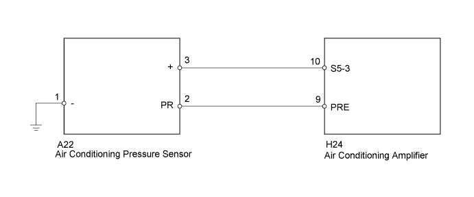
DTC B1423/23 Pressure Sensor Circuit |
| DTC Code | DTC Detection Condition | Trouble Area |
| B1423/23 |
|
|
| 1.CHECK REFRIGERANT PRESSURE |
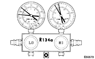 |
Install the manifold gauge set (Click here).
Read the manifold gauge pressure when the following conditions are established.
Prepare the vehicle in accordance with the chart below.
| Item | Condition |
| Engine speed | 1500 rpm |
| Vehicle doors | Fully open |
| Temperature setting | MAX COLD |
| Blower speed | HI |
| A/C switch | ON |
| Air inlet | RECIRC |
When the refrigerant volume is correct, the gauge reading indicates as follows:
| Refrigerant Pressure | Specified Condition |
| Low pressure side | 0.15 to 0.25 MPa (1.5 to 2.5 kgf/cm2, 22 to 36 psi) |
| High pressure side | 1.37 to 1.57 MPa (14 to 16 kgf/cm2, 199 to 228 psi) |
|
| ||||
| OK | |
 |
| 2.READ VALUE USING TECHSTREAM (REGULATOR PRESSURE SENSOR) |
Warm up the engine.
Turn the ignition switch off.
Connect the Techstream to the DLC3.
Turn the ignition switch to ON.
Turn the Techstream on.
Enter the following menus: Body Electrical / Air Conditioner / Data List / Regulator Pressure Sensor.
According to the display on the Techstream, read the Data List.
| Tester Display | Measurement Item/Range | Normal Condition | Diagnostic Note |
| Regulator Pressure Sensor | Regulator pressure sensor / Min.: 0 kgf/cm2G, Max.: 38.25 kgf/ cm2G | Actual refrigerant pressure is displayed | - |
| Result | Proceed to |
| NG | A |
| OK (When troubleshooting according to Problem Symptoms Table) | B |
| OK (When troubleshooting according to the DTC output) | C |
|
| ||||
|
| ||||
| A | |
|
| 3.INSPECT AIR CONDITIONING PRESSURE SENSOR |
 |
Install the manifold gauge set (Click here).
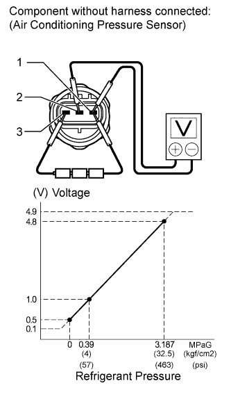
Disconnect the A22 air conditioning pressure sensor connector.
Connect the three 1.5 V dry cell batteries' positive (+) lead to terminal 3, and the negative (-) lead to terminal 1.
Connect the voltmeter positive (+) lead to terminal 2, and the negative (-) lead to terminal 1.
Measure the voltage according to the value(s) in the table below.
| Tester Connection | Condition | Specified Condition |
| 1 - 2 | Refrigerant pressure: 0.39 to 3.187 MPa (4 to 32.5 kgf/cm2, 57 to 463 psi) | 1.0 to 4.8 V |
Reconnect the air conditioning pressure sensor connector.
|
| ||||
| OK | |
|
| 4.CHECK HARNESS AND CONNECTOR (A/C PRESSURE SENSOR - A/C AMPLIFIER, BODY GROUND) |
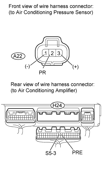 |
Disconnect the A22 air conditioning pressure sensor connector.
Disconnect the H24 air conditioning amplifier connector.
Measure the resistance according to the value(s) in the table below.
| Tester Connection | Condition | Specified Condition |
| A22-1 (-) - Body ground | Always | Below 1 Ω |
| A22-2 (PR) - H24-9 (PRE) | Always | Below 1 Ω |
| A22-3 (+) - H24-10 (S5-3) | Always | Below 1 Ω |
| A22-2 (PR) - Body ground | Always | 10 kΩ or higher |
| A22-3 (+) - Body ground | Always | 10 kΩ or higher |
Reconnect the air conditioning amplifier connector.
Reconnect the A/C pressure sensor connector.
|
| ||||
| OK | ||
 | ||
| ||
| 5.CHECK FOR A/C SYSTEM LEAK |
Install the manifold gauge set (Click here).
Recover the refrigerant from the A/C system using a refrigerant recovery unit.
Evacuate the A/C system and check that vacuum can be maintained in it.
|
| ||||
| OK | |
|
| 6.CHARGE REFRIGERANT |
Add an appropriate amount of refrigerant .
| NEXT | |
|
| 7.RECHECK DTC |
Recheck for the DTC when the following conditions are satisfied.
| Item | Condition |
| Vehicle Doors | Fully open |
| Temperature Setting | MAX COLD |
| Blower Speed | HI |
| A/C Switch | ON |
| R/F Switch | RECIRCULATION |
| Interior Temperature | 25 to 35°C (77 to 95°F) or higher |
| Engine Speed | 2000 rpm |
| Result | Proceed to |
| DTC B1423 is output | A |
| DTC B1423 is not output | B |
|
| ||||
| A | ||
| ||
| ||
| 8.REPAIR A/C SYSTEM LEAK |
Identify the area where refrigerant leaks from .
Repair the identified area of the A/C system.
Evacuate the A/C system.
| NEXT | |
|
| 9.CHARGE REFRIGERANT |
Use a refrigerant recovery unit to recover refrigerant.
Evacuate the A/C system.
Add an appropriate amount of refrigerant .
| NEXT | |
|
| 10.RECHECK DTC |
Recheck for the DTC when the following conditions are satisfied.
| Item | Condition |
| Vehicle Doors | Fully open |
| Temperature Setting | MAX COLD |
| Blower Speed | HI |
| A/C Switch | ON |
| R/F Switch | RECIRCULATION |
| Interior Temperature | 25 to 35°C (77 to 95°F) or higher |
| Engine Speed | 2000 rpm |
| Result | Proceed to |
| DTC B1423 is output | A |
| DTC B1423 is not output | B |
|
| ||||
| A | ||
| ||
| ||

