Terminal No. (Symbol)
| Wiring Color
| Terminal Description
| Condition
| Specified Condition
|
A43-1 (B) - A43-12 (GND)
| BE - BR
| Battery
| Ignition switch ON
| 11 to 14 V
|
A43-8 (CANH) - A43-12 (GND)
| BE - BR
| CAN communication signal
| CAN communication circuit
| Pulse generation
|
A43-9 (CANL) - A43-12 (GND)
| W - BR
| CAN communication signal
| CAN communication circuit
| Pulse generation
|
A43-10 (SGND) - Body ground
| BR - Body ground
| Ground
| Always
| Below 1 Ω
|
A43-12 (GND) - Body ground
| BR - Body ground
| Ground
| Always
| Below 1 Ω
|
A43-13 (IGB) - A43-12 (GND)
| L - BR
| Ignition switch ON signal
| Ignition switch off
| Below 1 V
|
A43-13 (IGB) - A43-12 (GND)
| L - BR
| Ignition switch ON signal
| Ignition switch ON
| 11 to 14 V
|
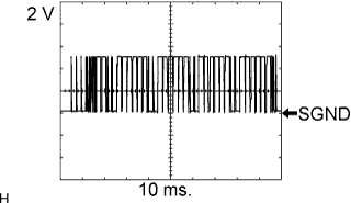
A43-22 (LRDD) - A43-10 (SGND)
| V - BR
| Laser radar sensor input signal
| Ignition switch ON
| Pulse generation
(see waveform 1)
|
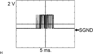
A43-23 (LRRD) - A43-10 (SGND)
| P - BR
| Laser radar sensor output signal
| Ignition switch ON
| Pulse generation
(see waveform 2)
|
A43-16 (MODE) - A43-12 (GND)
| P - BR
| Steering pad switch signal (Distance control switch signal)
| Ignition switch ON, Steering pad switch signal ON
| Below 2 V
|
A43-16 (MODE) - A43-12 (GND)
| P - BR
| Steering pad switch signal (Distance control switch signal)
| Ignition switch ON, Steering pad switch signal OFF
| 11 to 14 V
|
Terminal No. (Symbol)
| Wiring Color
| Terminal Description
| Condition
| Specified Condition
|
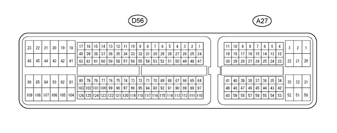
A27-26 (STP) - D56-81 (E1)
| LG - BR
| Stop light signal
| Brake pedal released (Stop light switch off)
| Below 1 V
|
A27-26 (STP) - D56-81 (E1)
| LG - BR
| Stop light signal
| Brake pedal depressed (Stop light switch on)
| 11 to 14 V
|
A27-35 (ST1-) - D56-81 (E1)
| R - BR
| Stop light signal
| Ignition switch ON, Brake pedal depressed (Stop light switch on)
| Below 1 V
|
A27-35 (ST1-) - D56-81 (E1)
| R - BR
| Stop light signal
| Ignition switch ON, Brake pedal released (Stop light switch off)
| 11 to 14 V
|
A27-16 (TC) - D56-81 (E1)
| R - BR
| Terminal TC of DLC3
| Ignition switch ON
| 11 to 14 V
|
A27-16 (TC) - D56-81 (E1)
| R - BR
| Terminal TC of DLC3
| Connect terminals TC and CG of DLC3
| Below 1 V
|
A27-44 (LGND) - Body ground
| GR - Body ground
| Ground
| Always
| Below 1 Ω
|
A27-45 (CCS) - D56-81 (E1)
| BR - BR
| Cruise control main switch signal
| Ignition switch ON
| 11 to 14 V
|
A27-45 (CCS) - D56-81 (E1)
| BR - BR
| Cruise control main switch signal
| CANCEL switch on
| 6.6 to 10.1 V
|
A27-45 (CCS) - D56-81 (E1)
| BR - BR
| Cruise control main switch signal
| - (COAST)/SET switch on
| 4.5 to 7.1 V
|
A27-45 (CCS) - D56-81 (E1)
| BR - BR
| Cruise control main switch signal
| + (ACCEL)/RES (RESUME) switch on
| 2.3 to 4.0 V
|
A27-45 (CCS) - D56-81 (E1)
| BR - BR
| Cruise control main switch signal
| Main switch on
| Below 1 V
|
A27-37 (CCHG) - D56-81 (E1)
| L - BR
| Distance control switch signal
| Ignition switch ON, Cruise control main switch on, MODE switch on
| Below 1 V
|
A27-37 (CCHG) - D56-81 (E1)
| L - BR
| Distance control switch signal
| Ignition switch ON, Cruise control main switch on, MODE switch off
| 11 to 14 V
|
D56-81 (E1) - Body ground
| BR - Body ground
| Ground
| Always
| Below 1 Ω
|
Terminal No. (Symbol)
| Wiring Color
| Terminal Description
| Condition
| Specified Condition
|
A26-1 (LGND) - Body ground
| GR - Body ground
| Ground (Distance signal)
| Always
| Below 1 Ω
|
A26-2 (SGND) - Body ground
| BR - Body ground
| Ground
| Always
| Below 1 Ω
|
A26-3 (LRDD) - A26-2 (SGND)
| V - BR
| Laser radar sensor output signal
| Ignition switch ON
| Pulse generation
(see waveform 1)
|
A26-4 (LRRD) - A26-2 (SGND)
| P - BR
| Laser radar sensor input signal
| Ignition switch ON
| Pulse generation
(see waveform 2)
|
A26-5 (IGB) - A26-2 (SGND)
| L - BR
| Power source
| Ignition switch ON
| 11 to 14 V
|
Terminal No. (Symbol)
| Wiring Color
| Terminal Description
| Condition
| Specified Condition
|
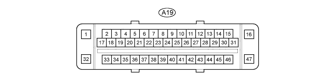
A19-9 (BZ) - Body ground
| Y - Body ground
| Skid control buzzer circuit
| Ignition switch ON
Skid control buzzer is sounded
| Below 1 V ←→ 11 to 14 V
|
Ignition switch ON
Skid control buzzer is not sounded
| 11 to 14 V
|
A19-15 (STPO) - Body ground
| BR - Body ground
| Stop light control relay output signal
| Ignition switch ON
| 11 to 14 V
|
A19-6 (STP2) - Body ground
| GR - Body ground
| Stop light control relay input signal
| Brake pedal released
(Stop light switch OFF)
| Below 1.0 V
|
Brake pedal depressed
(Stop light switch ON)
| 11 to 14 V
|
A19-38 (STP) - Body ground
| Y - Body ground
| Stop light switch input signal
| Brake pedal released
(Stop light switch OFF)
| Below 1.0 V
|
Brake pedal depressed
(Stop light switch ON)
| 11 to 14 V
|