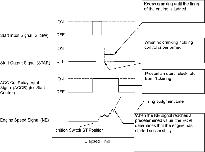
SFI SYSTEM > Cranking Holding Function Circuit |
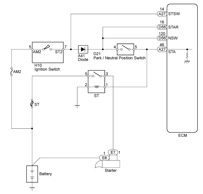
| 1.CHECK CRANKING |
Check the cranking of the engine.
| Test Result | Proceed to |
| Cranking possible and holding control operates | A |
| Does not crank | B |
| Cranking possible but holding control does not operate | C |
|
| ||||
|
| ||||
| A | ||
 | ||
| ||
| 2.READ VALUE USING TECHSTREAM (STARTER SIGNAL) |
Connect the Techstream to the DLC3.
Turn the ignition switch to ON.
Turn the Techstream on.
Enter the following menus: Powertrain / Engine and ECT / Data List / Starter Signal.
Read values.
Check the result when the ignition switch is turned to ON and when the engine is started.
| Ignition Switch Position | Display (Starter Signal) |
| ON | Close |
| START | Open |
|
| ||||
| OK | |
 |
| 3.INSPECT STARTER RELAY (ST) |
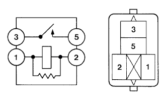 |
Remove the starter relay (ST) from the engine room relay block .
Measure the resistance according to the value(s) in the table below.
| Tester Connection | Condition | Specified Condition |
| 3 - 5 | When no battery voltage applied to terminals 1 and 2 | 10 kΩ or higher |
| 3 - 5 | When battery voltage applied to terminals 1 and 2 | Below 1 Ω |
|
| ||||
| OK | |
|
| 4.CHECK HARNESS AND CONNECTOR (ST RELAY - PNP SWITCH) |
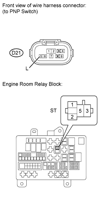 |
Remove the ST relay from the engine room relay block.
Disconnect the D21 PNP switch.
Measure the resistance according to the value(s) in the table below.
| Tester Connection | Condition | Specified Condition |
| ST relay (1) - D21-5 (L) | Always | Below 1 Ω |
| ST relay (1) or D21-5 (L) - Body ground | Always | 10 kΩ or higher |
|
| ||||
| OK | |
|
| 5.CHECK STARTER RELAY (POWER SOURCE) |
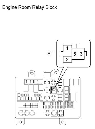 |
Remove the ST relay from the engine room relay block.
Measure the voltage according to the value(s) in the table below.
| Tester Connection | Condition | Specified Condition |
| ST relay (2) - ST relay (5) | Always | 11 to 14 V |
|
| ||||
| OK | |
|
| 6.INSPECT STARTER |
Inspect the starter (Click here).
|
| ||||
| OK | ||
| ||
| ||
| 7.CHECK IGNITION SWITCH (POWER SOURCE) |
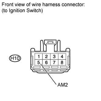 |
Disconnect the H10 ignition switch connector.
Measure the voltage according to the value(s) in the table below.
| Tester Connection | Condition | Specified Condition |
| H10-5 (AM2) - Body ground | Always | 11 to 14 V |
|
| ||||
| OK | |
|
| 8.INSPECT IGNITION SWITCH |
Inspect the ignition switch (Click here).
|
| ||||
| OK | |
|
| 9.INSPECT PARK / NEUTRAL POSITION SWITCH (POWER SOURCE) |
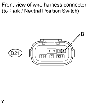 |
Disconnect the D21 PNP switch connector.
Measure the voltage according to the value(s) in the table below.
| Tester Connection | Condition | Specified Condition |
| D21-4 (B) - Body ground | While cranking the engine | 11 to 14 V |
|
| ||||
| OK | |
|
| 10.INSPECT PARK / NEUTRAL POSITION SWITCH |
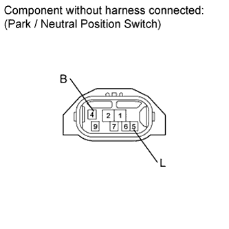 |
Disconnect the D21 PNP switch connector.
Measure the resistance according to the value(s) in the table below.
| Tester Connection | Switch Condition | Specified Condition |
| 4 (B) - 5 (L) | Shift lever position P | Below 1 Ω |
| Shift lever position N | Below 1 Ω |
| Result | Proceed to |
| OK | A |
| NG (for 2WD) | B |
| NG (for 4WD) | C |
|
| ||||
|
| ||||
| A | ||
| ||
| ||
| 11.CHECK HARNESS AND CONNECTOR (IGNITION SWITCH - ECM) |
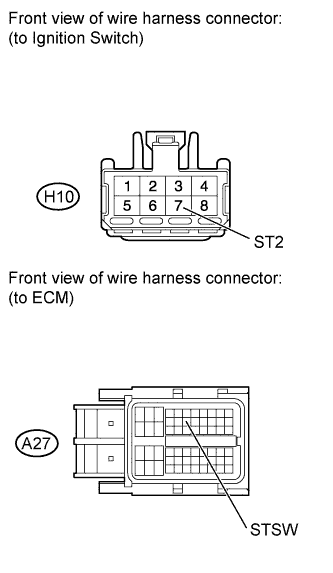 |
Disconnect the H10 ignition switch connector.
Disconnect the A27 ECM connector.
Measure the resistance according to the value(s) in the table below.
| Tester Connection | Condition | Specified Condition |
| H10-7 (ST2) - A27-14 (STSW) | Always | Below 1 Ω |
| H10-7 (ST2) or A27-14 (STSW) - Body ground | Always | 10 kΩ or higher |
|
| ||||
| OK | |
|
| 12.CHECK HARNESS AND CONNECTOR (PNP SWITCH - ECM) |
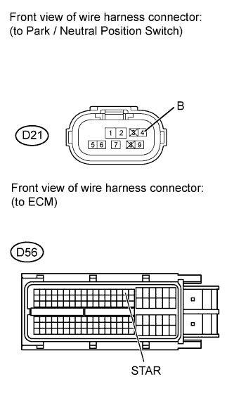 |
Disconnect the D21 PNP switch connector.
Disconnect the D56 ECM connector.
Measure the resistance according to the value(s) in the table below.
| Tester Connection | Condition | Specified Condition |
| D21-4 (B) - D56-16 (STAR) | Always | Below 1 Ω |
| D21-4 (B) or D56-16 (STAR) - Body ground | Always | 10 kΩ or higher |
|
| ||||
| OK | ||
| ||
| ||

