 |
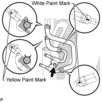
Install the No. 2 oil cooler inlet hose and No. 2 oil cooler outlet hose to the No. 2 oil cooler tube.
- NOTICE:
- Make sure the paint marks and pinching portion of each clip are facing the directions shown in the illustration.
AIR COOLED OIL COOLER > INSTALLATION |
| 1. INSTALL NO. 2 OIL COOLER TUBE |
|
Install the No. 2 oil cooler inlet hose and No. 2 oil cooler outlet hose to the No. 2 oil cooler tube.
Install the No. 2 oil cooler tube together with the 2 oil cooler hoses with the bolt.
Connect the No. 2 oil cooler inlet hose and No. 2 oil cooler outlet hose to the cooler condenser.
| 2. INSTALL COOLER CONDENSER ASSEMBLY (AIR COOLED OIL COOLER) |
Install the cooler condenser (Click here).
| 3. INSTALL OIL COOLER TUBE |
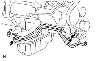 |
Install the oil cooler tube with the 2 bolts.
| 4. INSTALL OIL COOLER ACCESSORY ASSEMBLY |
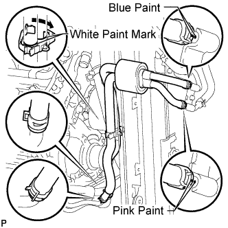 |
Install the oil cooler accessory assembly to the oil cooler tube, and then pass the 2 hoses through the No. 1 flexible hose clamp and close the clamp as shown in the illustration.
Connect the 2 hoses to the No. 2 oil cooler tube.
| 5. INSTALL NO. 1 OIL COOLER INLET HOSE AND NO. 1 OIL COOLER OUTLET HOSE |
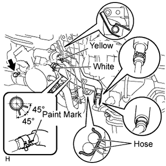 |
Connect the No. 1 oil cooler inlet hose and No. 1 oil cooler outlet hose to the oil cooler tube.
Connect the 2 hoses to the transmission oil thermostat to install them.
Install the bolt to fix the water by-pass pipe in place.
| 6. ADD AUTOMATIC TRANSMISSION FLUID |
Add automatic transmission fluid (Click here).
| 7. INSTALL FRONT BUMPER ASSEMBLY |
Install the front bumper (Click here).