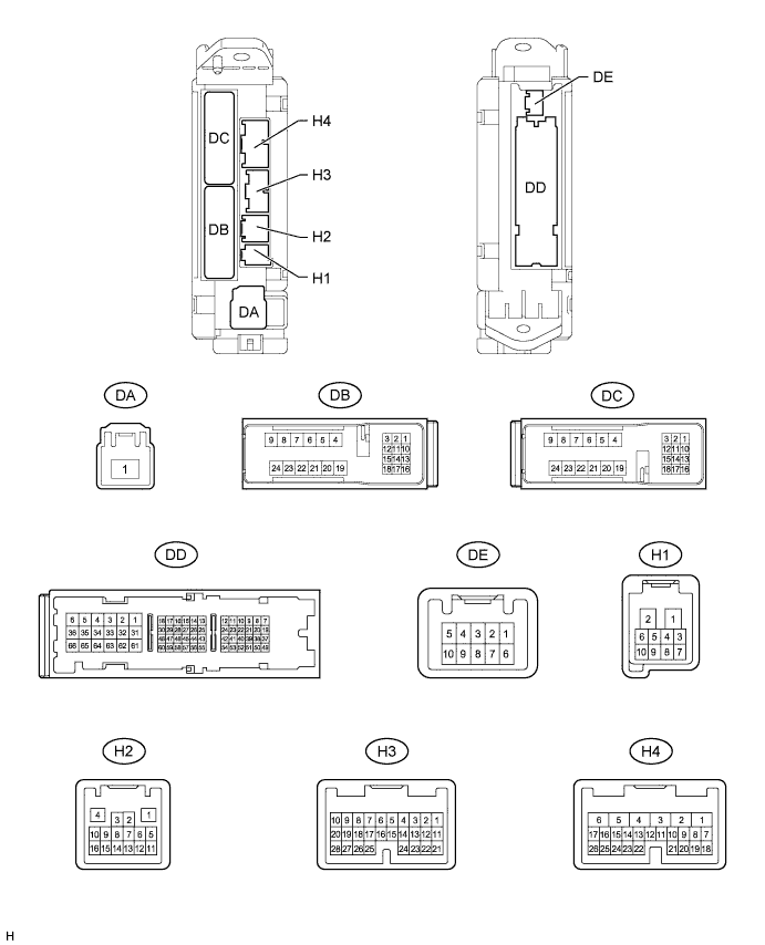
WIRELESS DOOR LOCK CONTROL SYSTEM > TERMINALS OF ECU |
| CHECK MAIN BODY ECU (COWL SIDE JUNCTION BLOCK LH) |
Disconnect the DA, DB, DC, DD, H1, H3 and H4 main body ECU connectors.
Measure the resistance and voltage between each terminal of the wire harness side connectors and body ground.
| Terminal No (Symbol.) | Wiring Color | Terminal Description | Condition | Specified Condition |
| DB-13 (BECU) - Body ground | GR - Body ground | +B power supply | Always | 11 to 14 V |
| DA-1 (ALTB) - Body ground | B - Body ground | +B (power system alternator system) power supply | Always | 11 to 14 V |
| H4-24 (DCTY) - Body ground | BR - Body ground | Driver side door courtesy light switch input | Driver side door CLOSED (OFF) → OPEN (ON) | 10 kΩ or higher → Below 1 Ω |
| H3-21 (PCTY) - Body ground | BE - Body ground | Passenger side courtesy light switch input | Passenger side door CLOSED (OFF) → OPEN (ON) | 10 kΩ or higher → Below 1 Ω |
| H3-25 (RRCY) - Body ground | L - Body ground | Rear courtesy light switch RH input | Rear door RH CLOSED (OFF) → OPEN (ON) | 10 kΩ or higher → Below 1 Ω |
| DC-2 (LCTY) - Body ground | G - Body ground*1 B - Body ground*2 | Rear courtesy light switch LH input | Rear door LH CLOSED (OFF) → OPEN (ON) | 10 kΩ or higher → Below 1 Ω |
| H1-5 (KSW) - Body ground | LG - Body ground | Unlock warning switch input | No key in ignition key cylinder (OFF) → Key inserted (ON) | 10 kΩ or higher → Below 1 Ω |
| DD-62 (GND1, 2) - Body ground | W-B - Body ground | Ground | Always | Below 1 Ω |
Reconnect the DA, DB, DC, DD, H1, H3 and H4 main body ECU connectors.
Measure the voltage between each terminal of the wire harness side connectors and body ground.
| Terminal No. (Symbol) | Wiring Color | Terminal Description | Condition | Specified Condition |
| H2-4 (HAZ) - Body ground | BE - Body ground | Turn signal flasher relay signal | Any transmitter switch is pressed → not pressed | Below 1 V → Pulse generation*1 |
| H1-7 (BZR) - Body ground | R - Body ground | Wireless door lock buzzer | Wireless door lock buzzer OFF → ON | Below 1 V → 11 to 14 V |
| CHECK BACK DOOR ECU |
Disconnect the V2 and V3 back door ECU connectors.
Measure the resistance and voltage between each terminal of the wire harness side connectors and body ground.
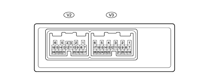
| Terminal No. (Symbol) | Wiring Color | Terminal Description | Condition | Specified Condition |
| V2-1 (BDR) - Body ground | SB - Body ground | +B power source | Always | 11 to 14 V |
| V2-7 (BECU) - Body ground | GR - Body ground | +B power source | Always | 11 to 14 V |
| V2-6 (GND) - Body ground | W-B - Body ground | Power ground | Always | Below 1 Ω |
| V3-10 (BDCY) - V3-20 (CTYE) | P - R | Back door courtesy switch | Back door CLOSED → OPEN | 10 kΩ or higher → Below 1 Ω |