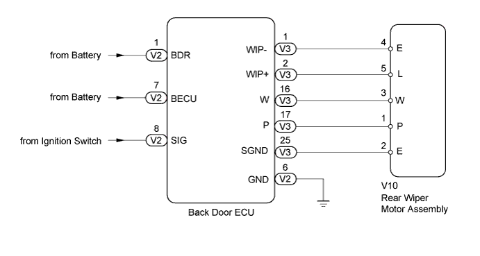
WIPER AND WASHER SYSTEM > Rear Wiper Motor Circuit |
| 1.CHECK DTC OUTPUT |
Connect the Techstream to the DLC3.
Turn the ignition switch to ON.
Turn the Techstream on.
Clear the DTCs.
Check whether DTC B1287 or B2325 recurs 10 seconds or more after the ignition switch is turned to ON.
|
| ||||
| OK | |
 |
| 2.PERFORM ACTIVE TEST USING TECHSTREAM (REAR WIPER) |
Connect the Techstream to the DLC3.
Turn the ignition switch to ON.
Turn the Techstream on.
Enter the following menus: Body Electrical / Back Door P/W / Active Test.
According to the display on the Techstream, perform the Active Test.
| Tester Display | Test Part | Control Range | Diagnostic Note |
| Rear Wiper Active | Rear Wiper motor operation | STOP/ACTIVE | - |
|
| ||||
| OK | ||
 | ||
| ||
| 3.CHECK HARNESS AND CONNECTOR (BACK DOOR ECU - BATTERY, IGNITION SWITCH, BODY GROUND) |
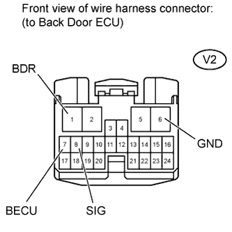 |
Disconnect the V2 back door ECU connector.
Measure the voltage according to the value(s) in the table below.
| Tester Connection | Switch Condition | Specified Condition |
| V2-1 (BDR) - Body ground | Always | 11 to 14 V |
| V2-7 (BECU) - Body ground | Always | 11 to 14 V |
| V2-8 (SIG) - Body ground | Ignition Switch OFF → ON | Below 1 V → 11 to 14 V |
Measure the resistance according to the value(s) in the table below.
| Tester Connection | Condition | Specified Condition |
| V2-6 (GND) - Body ground | Always | Below 1 Ω |
Reconnect the back door ECU connector.
|
| ||||
| OK | |
|
| 4.INSPECT REAR WIPER MOTOR ASSEMBLY |
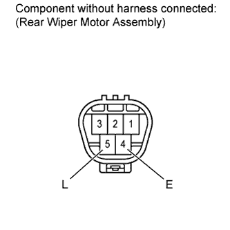 |
Remove the rear wiper motor assembly.
Connect the battery positive (+) lead to terminal 5 (L) and the negative (-) lead to terminal 4 (E).
Check that the rear wiper motor operates.
Reinstall the rear wiper motor assembly.
|
| ||||
| OK | |
|
| 5.CHECK HARNESS AND CONNECTOR (REAR WIPER MOTOR ASSEMBLY - BACK DOOR ECU) |
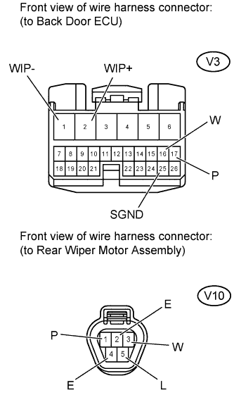 |
Disconnect the V3 back door ECU connector.
Disconnect the V10 rear wiper motor assembly connector.
Measure the resistance according to the value(s) in the table below.
| Tester Connection | Condition | Specified Condition |
| V3-1 (WIP-) - V10-4 (E) | Always | Below 1 Ω |
| V3-1 (WIP-) or V10-4 (E) - Body ground | Always | 10 kΩ or higher |
| V3-2 (WIP+) - V10-5 (L) | Always | Below 1 Ω |
| V3-2 (WIP+) or V10-5 (L) - Body ground | Always | 10 kΩ or higher |
| V3-16 (W) - V10-3 (W) | Always | Below 1 Ω |
| V3-16 (W) or V10-3 (W) - Body ground | Always | 10 kΩ or higher |
| V3-17 (P) - V10-1 (P) | Always | Below 1 Ω |
| V3-17 (P) or V10-1 (P) - Body ground | Always | 10 kΩ or higher |
| V3-25 (SGND) - V10-2 (E) | Always | Below 1 Ω |
| V3-25 (SGND) or V10-2 (E) - Body ground | Always | 10 kΩ or higher |
Reconnect the rear wiper motor assembly connector.
Reconnect the back door ECU connector.
|
| ||||
| OK | ||
| ||
| ||

