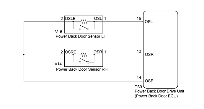
POWER BACK DOOR SYSTEM > Touch Sensor Circuit |
| 1.READ VALUE USING TECHSTREAM (POWER BACK DOOR TOUCH SENSOR) |
Connect the Techstream to the DLC3.
Turn the ignition switch to ON.
Turn the Techstream on.
Enter the following menus: Body Electrical / Back Door / Data List /
According to the display on the Techstream, read the Data List.
| Tester Display | Measurement Item/Range | Normal Condition | Diagnostic Note |
| PBD Touch Sen L | Power back door touch sensor LH signal / ON or OFF | ON: Power back door touch sensor LH is pressed OFF: Power back door touch sensor LH is not pressed | - |
| PBD Touch Sen R | Power back door touch sensor RH signal / ON or OFF | ON: Power back door touch sensor RH is pressed OFF: Power back door touch sensor RH is not pressed | - |
|
| ||||
| OK | ||
 | ||
| ||
| 2.INSPECT POWER BACK DOOR TOUCH SENSOR |
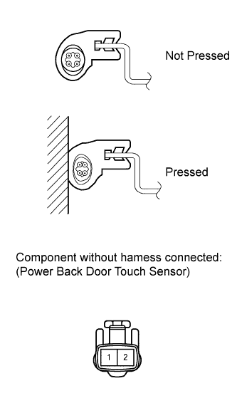 |
Remove the power back door touch sensor (Click here).
Measure the resistance according to the value(s) in the table below.
| Tester Connection | Condition | Specified Condition |
| 1 - 2 | Not pressed | 950 to 1050 Ω |
| 1 - 2 | Pressed | Below 100 Ω |
Reinstall the power back door touch sensor.
|
| ||||
| OK | |
 |
| 3.CHECK HARNESS AND CONNECTOR (POWER BACK DOOR TOUCH SENSOR - POWER BACK DOOR DRIVE UNIT AND BODY GROUND) |
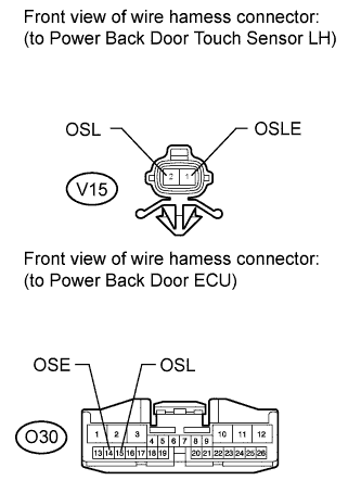 |
LH Side
Disconnect the V15 sensor connectors.
Disconnect the O30 ECU connector.
Measure the resistance according to the value(s) in the table below.
| Tester Connection | Condition | Specified Condition |
| V15-1 (OSL) - O30-15 (OSL) | Always | Below 1 Ω |
| V15-2 (OSLE) - O30-14 (OSE) | Always | Below 1 Ω |
| V15-1 (OSL) - Body ground | Always | 10 kΩ or higher |
| V15-2 (OSLE) - Body ground | Always | Below 1 Ω |
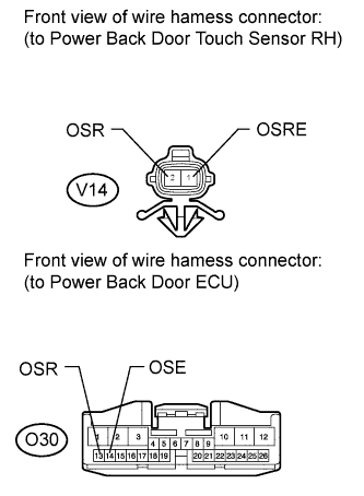 |
RH Side
Disconnect the V14 sensor connectors.
Disconnect the O30 ECU connector.
Measure the resistance according to the value(s) in the table below.
| Tester Connection | Condition | Specified Condition |
| V14-1 (OSR) - O30-13 (OSR) | Always | Below 1 Ω |
| V14-2 (OSRE) - O30-14 (OSE) | Always | Below 1 Ω |
| V14-1 (OSR) - Body ground | Always | 10 kΩ or higher |
| V14-2 (OSRE) - Body ground | Always | Below 1 Ω |
Reconnect the sensor connectors.
Reconnect the ECU connector.
|
| ||||
| OK | ||
| ||
| ||

