 |
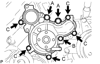
Install a new gasket and the engine water pump with the 8 bolts shown in the illustration.
- Torque:
- for bolt A:
- 47 N*m{ 479 kgf*cm , 35 ft.*lbf }
- for bolt B:
- 23 N*m{ 235 kgf*cm , 17 ft.*lbf }
- for bolt C:
- 20 N*m{ 204 kgf*cm , 15 ft.*lbf }
WATER PUMP > INSTALLATION |
| 1. INSTALL ENGINE WATER PUMP ASSEMBLY |
|
Install a new gasket and the engine water pump with the 8 bolts shown in the illustration.
| 2. INSTALL WATER PUMP PULLEY |
Temporarily install the pulley with the 4 bolts.
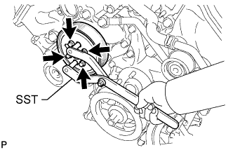 |
Using SST, hold the pulley and tighten the 4 bolts.
| 3. INSTALL WATER INLET HOUSING |
Install a new gasket to the water pump.
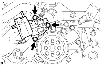 |
Install the water inlet housing with the 3 bolts.
| 4. CONNECT NO. 5 WATER BY-PASS HOSE |
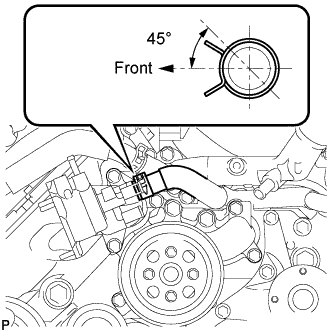 |
Connect the water by-pass hose.
| 5. CONNECT NO. 8 WATER BY-PASS HOSE |
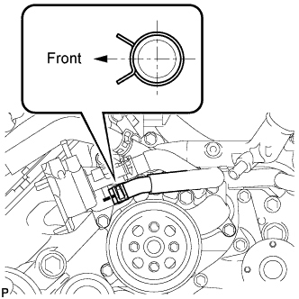 |
Connect the water by-pass hose.
| 6. INSTALL NO. 1 WATER BY-PASS HOSE |
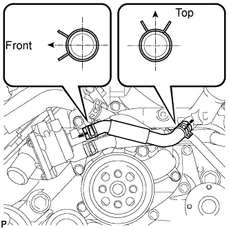 |
Install the water by-pass hose.
| 7. INSTALL WATER BY-PASS PIPE (w/ Oil Cooler) |
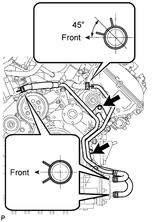 |
Connect the 4 water hoses.
Install the water by-pass hose with the 2 bolts.
| 8. CONNECT COOLER COMPRESSOR ASSEMBLY (w/ Oil Cooler) |
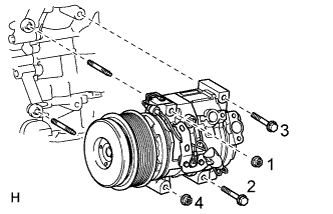 |
Install the cooler compressor and 2 stud bolts.
Install the 2 bolts and 2 nuts.
Connect the connector.
| 9. INSTALL FRONT FENDER APRON SEAL LH |
Install the fender apron seal with the 6 clips.
| 10. INSTALL INLET RADIATOR HOSE |
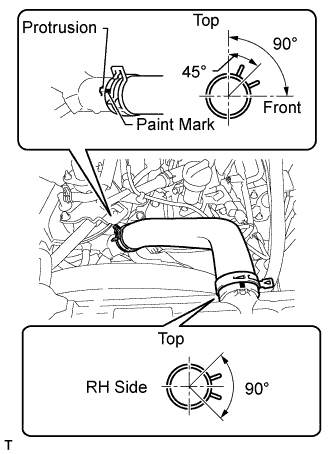 |
Install the inlet radiator hose.
| 11. INSTALL FAN SHROUD |
Install the fan pulley to the fan bracket.
Place the fan shroud together with the fluid coupling fan between the radiator and engine.
Temporarily install the fluid coupling fan to the fan bracket with the 4 nuts. Tighten the nuts as much as possible by hand.
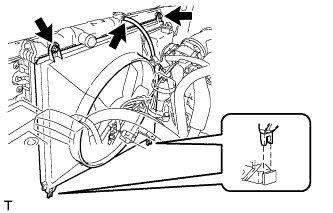 |
Attach the shroud's claws to the radiator as shown in the illustration.
Install the shroud with the 2 bolts.
Connect the reservoir hose to the upper radiator tank.
Install the fan and generator V-belt .
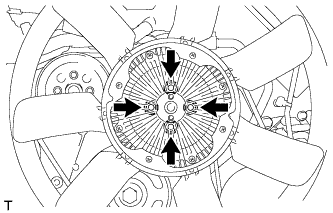 |
Tighten the 4 nuts of the fluid coupling fan.
| 12. INSTALL WATER INLET SUB-ASSEMBLY WITH THERMOSTAT |