 |
Apply a light coat of engine oil to the camshaft journals, camshaft housings and bearing caps.
CAMSHAFT (for Bank 1) > INSTALLATION |
| 1. INSTALL CAMSHAFT BEARING CAP LH |
|
Apply a light coat of engine oil to the camshaft journals, camshaft housings and bearing caps.
Install the No. 3 and No. 4 camshafts to the camshaft housing.
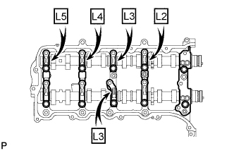
Confirm the marks and numbers on the camshaft bearing caps and place them in their proper positions and directions.
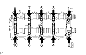 |
Temporarily install the 10 bolts in the order shown in the illustration.
| 2. INSTALL CAMSHAFT HOUSING SUB-ASSEMBLY LH |
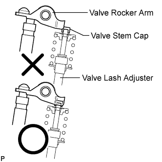 |
Install the valve rocker arms as shown in the illustration.
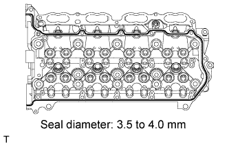 |
Apply seal packing in a continuous line as shown in the illustration.
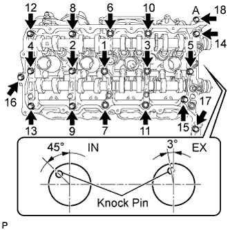 |
Install the camshaft housing, and install the 18 bolts in the order shown in the illustration.
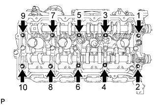 |
Tighten the 10 bolts in the order shown in the illustration.
| 3. INSTALL NO. 3 CHAIN TENSIONER ASSEMBLY |
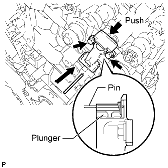 |
Install the chain tensioner with the 2 bolts.
While pushing down the No. 2 chain tensioner, insert a pin of φ1.0 mm (0.0394 in.) into the hole to fix it in place.
| 4. INSTALL NO. 1 CHAIN SUB-ASSEMBLY LH |
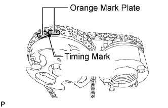 |
Align the No. 1 chain's orange mark plates with the camshaft timing gear's timing mark, and attach the chain to the gear as shown in the illustration.
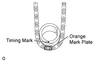 |
Align the No. 1 chain's orange mark plate with the crankshaft timing gear's timing mark, and attach the chain to the gear as shown in the illustration.
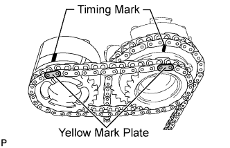 |
Align the No. 2 chain's yellow mark plates with the timing marks of the camshaft timing gear and camshaft timing exhaust gear, and attach the No. 2 chain to the gears as shown in the illustration.
Install the crankshaft timing sprocket to the crankshaft.
Align and attach the knock pin of the No. 3 camshaft with the pin hole of the camshaft timing gear.
Using the hexagonal portion of the No. 4 camshaft, align and attach the knock pin of the No. 4 camshaft with the pin hole of the camshaft timing exhaust gear.
Remove the pin from the No. 2 chain tensioner.
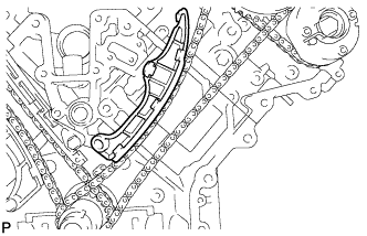
| 5. INSTALL NO. 1 CHAIN TENSIONER SLIPPER LH |
 |
| 6. INSTALL NO. 1 CHAIN TENSIONER ASSEMBLY LH |
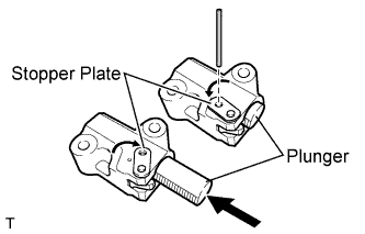 |
Move the stopper plate upward to release the lock, and push the plunger deep into the tensioner.
Move the stopper plate downward to set the lock, and insert a hexagon wrench into the hole of the stopper plate.
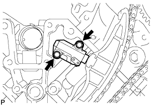 |
Install a new gasket and the chain tensioner with the 2 bolts.
| 7. INSTALL NO. 1 CHAIN VIBRATION DAMPER LH |
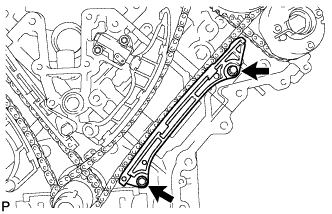 |
Install the vibration damper with the 2 bolts.
Remove the hexagon wrench from the No. 1 chain tensioner.
| 8. TIGHTEN CAMSHAFT TIMING GEAR LH |
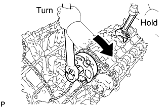 |
Using a wrench to hold the hexagonal portion of the No. 3 camshaft, tighten the camshaft timing gear with the bolt.
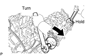 |
Using a wrench to hold the hexagonal portion of the No. 4 camshaft, tighten the camshaft timing exhaust gear with the bolt.
| 9. CHECK NO. 1 CYLINDER TO TDC / COMPRESSION |
Temporarily install the pulley set bolt.
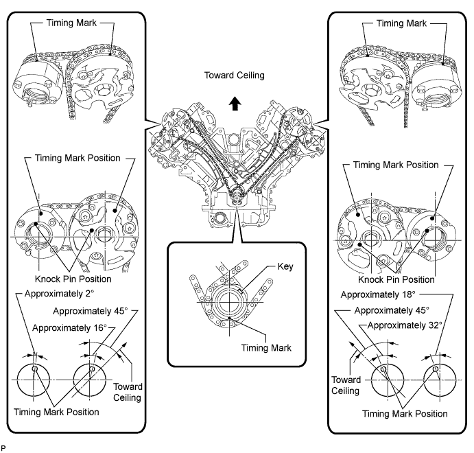
Rotate the crankshaft clockwise, and check that the timing marks on the crankshaft timing gear and camshaft timing gears are as shown in the illustration.
Remove the crankshaft pulley set bolt.
| 10. INSTALL TIMING CHAIN COVER SUB-ASSEMBLY |
Install the timing chain cover (Click here).
| 11. INSPECT IGNITION TIMING |
Warm up and stop the engine.
Allow the engine to warm up to a normal operating temperature.
When using the Techstream:
Connect the Techstream to the DLC3.
Start the engine and idle it.
Turn the Techstream main switch ON.
Enter the following menus: Powertrain / Engine and ECT / Data List / Primary / IGN Advance.
Disconnect the Techstream from the DLC3.
 |
When not using the Techstream:
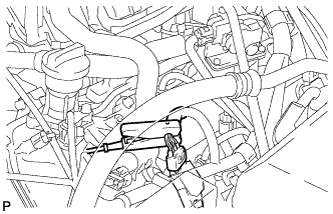
Connect the tester probe of a timing light to the wire of the ignition coil connector for the No. 1 cylinder.
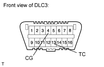 |
Using SST, connect terminals 13 (TC) and 4 (CG) of the DLC3.
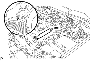 |
Using the timing light, check the ignition timing.
Remove SST from the DLC3.
Check the ignition timing.
Disconnect the timing light from the engine.
| 12. INSPECT ENGINE IDLE SPEED |
Warm up and stop the engine.
Allow the engine to warm up to a normal operating temperature.
When using the Techstream:
Connect the Techstream to the DLC3.
Race the engine at 2500 rpm for approximately 90 seconds.
Turn the Techstream main switch ON.
Enter the following menus: Powertrain / Engine and ECT / Data List / Primary / Engine Speed.
Disconnect the Techstream from the DLC3.
 |
When not using the Techstream:
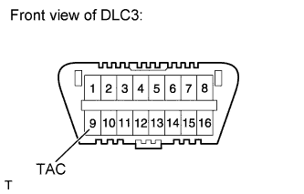
Using SST, connect the tachometer probe to terminal 9 (TAC) of the DLC3.
Race the engine at 2500 rpm for approximately 90 seconds.
Check the idle speed.
Disconnect the tachometer probe from the DLC3.