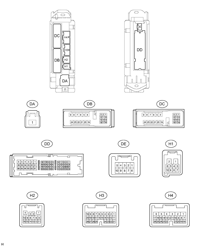
LIN COMMUNICATION SYSTEM > TERMINALS OF ECU |
| CHECK MAIN BODY ECU |
Disconnect the DA, DB, DD and H2 main body ECU connectors.
Measure the resistance and voltage according to the value(s) in the table below.
| Terminal No. (Symbol) | Wiring Color | Terminal Description | Condition | Specified Condition |
| H2-10 (LIN2) - Body ground | V - Body ground | LIN communication line | Ignition switch ON | Pulse generation |
| DA-1 (ALTB) - DD-62 (GND1) | B - W-B | Battery power supply | Always | 11 to 14 V |
| DB-13 (BECU) - DD-62 (GND1) | GR - W-B | Battery power supply | Always | 11 to 14 V |
| DD-62 (GND1) - Body ground | W-B - Body ground | Ground | Always | Below 1 Ω |
Reconnect the main body ECU connectors.
| CHECK POWER WINDOW REGULATOR MASTER SWITCH ASSEMBLY |
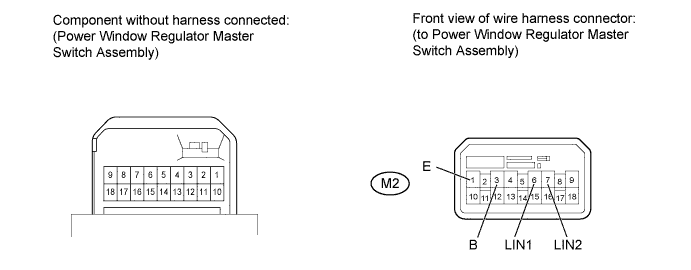
Disconnect the M2 power window regulator master switch assembly connector.
Measure the resistance and voltage according to the value(s) in the table below.
| Terminal No. (Symbol) | Wiring Color | Terminal Description | Condition | Specified Condition |
| M2-1 (E) - Body ground | W-B - Body ground | Ground | Always | Below 1 Ω |
| M2-3 (B) - M2-1 (E) | L - W-B | Battery power supply | Always | 11 to 14 V |
| M2-6 (LIN1) - Body ground | L - Body ground | LIN communication line | Ignition switch ON | Pulse generation |
| M2-7 (LIN2) - Body ground | W - Body ground | LIN communication line | Ignition switch ON | Pulse generation |
Reconnect the power window regulator master switch assembly connector.
| CHECK FRONT POWER WINDOW REGULATOR MOTOR ASSEMBLY LH |
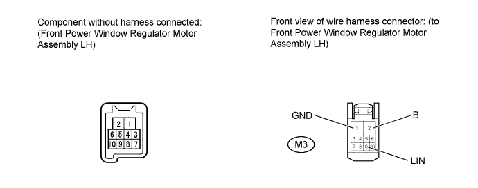
Disconnect the M3 front power window regulator motor assembly LH connector.
Measure the resistance and voltage according to the value(s) in the table below.
| Terminal No. (Symbol) | Wiring Color | Terminal Description | Condition | Specified Condition |
| M3-1 (GND) - Body ground | W-B - Body ground | Ground | Always | Below 1 Ω |
| M3-2 (B) - M3-1(GND) | G - W-B | Battery power supply | Always | 11 to 14 V |
| M3-9 (LIN) - Body ground | W - Body ground | LIN communication line | Ignition switch ON | Pulse generation |
Reconnect the front power window regulator motor assembly LH connector.
| CHECK FRONT POWER WINDOW REGULATOR MOTOR ASSEMBLY RH |
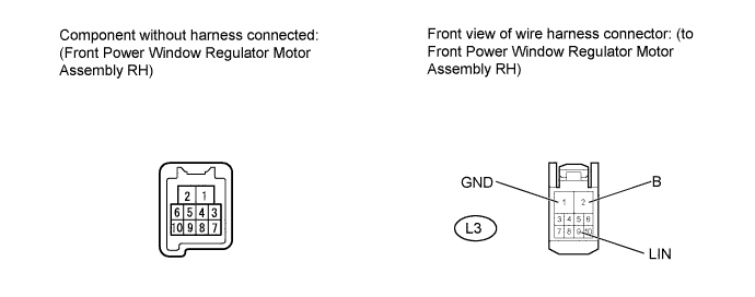
Disconnect the L3 front power window regulator motor assembly RH connector.
Measure the resistance and voltage according to the value(s) in the table below.
| Terminal No. (Symbol) | Wiring Color | Terminal Description | Condition | Specified Condition |
| L3-1 (GND) - Body ground | W-B - Body ground | Ground | Always | Below 1 Ω |
| L3-2 (B) - L3-1 (GND) | V - W-B | Battery power supply | Always | 11 to 14 V |
| L3-9 (LIN) - Body ground | L - Body ground | LIN communication line | Ignition switch ON | Pulse generation |
Reconnect the front power window regulator motor assembly RH connector.
| CHECK SLIDING ROOF DRIVE GEAR SUB-ASSEMBLY |
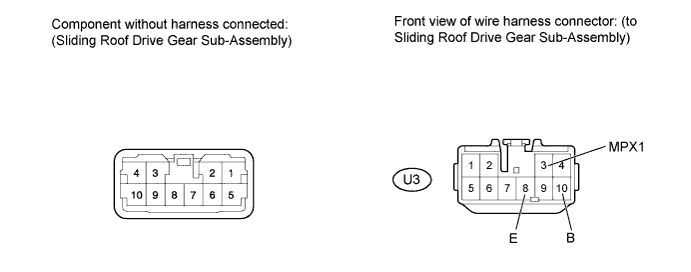
Disconnect the U3 sliding roof drive gear sub-assembly connector.
Measure the resistance and voltage according to the value(s) in the table below.
| Terminal No. (Symbol) | Wiring Color | Terminal Description | Condition | Specified Condition |
| U3-3 (MPX1) - Body ground | P - Body ground | LIN communication line | Ignition switch ON | Pulse generation |
| U3-8 (E) - Body ground | W-B - Body ground | Ground | Always | Below 1 Ω |
| U3-10 (B) - U3-8 (E) | L - W-B | Battery power supply | Always | 11 to 14 V |
Reconnect the sliding roof drive gear sub-assembly connector.
| CHECK BACK DOOR ECU |
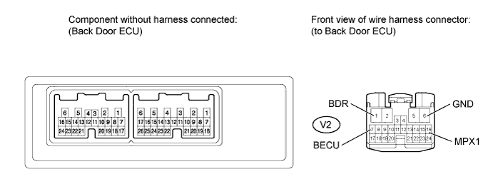
Disconnect the V2 back door ECU connector.
Measure the resistance and voltage according to the value(s) in the table below.
| Terminal No. (Symbol) | Wiring Color | Terminal Description | Condition | Specified Condition |
| V2-1 (BDR) - V2-6 (GND) | SB - W-B | Battery power supply | Always | 11 to 14 V |
| V2-6 (GND) - Body ground | W-B - Body ground | Ground | Always | Below 1 Ω |
| V2-7 (BECU) - V2-6(GND) | GR - W-B | Battery power supply | Always | 11 to 14 V |
| V2-16 (MPX1) - Body ground | Y - Body ground | LIN communication line | Ignition switch ON | Pulse generation |
Reconnect the back door ECU connector.