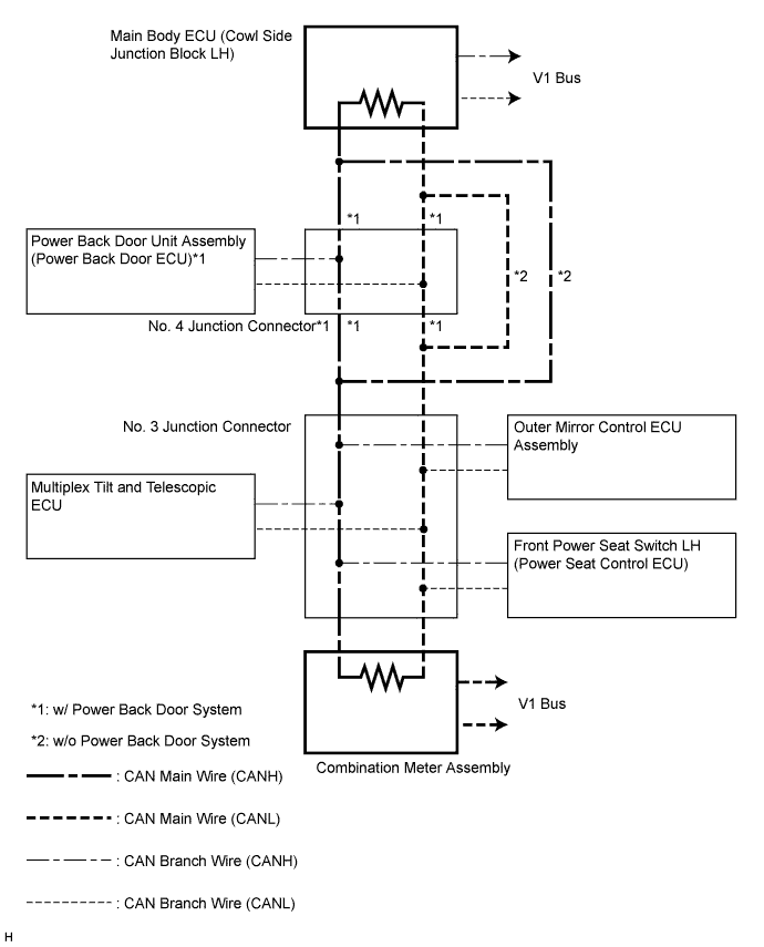
No.
| ECU/Sensor Name
|
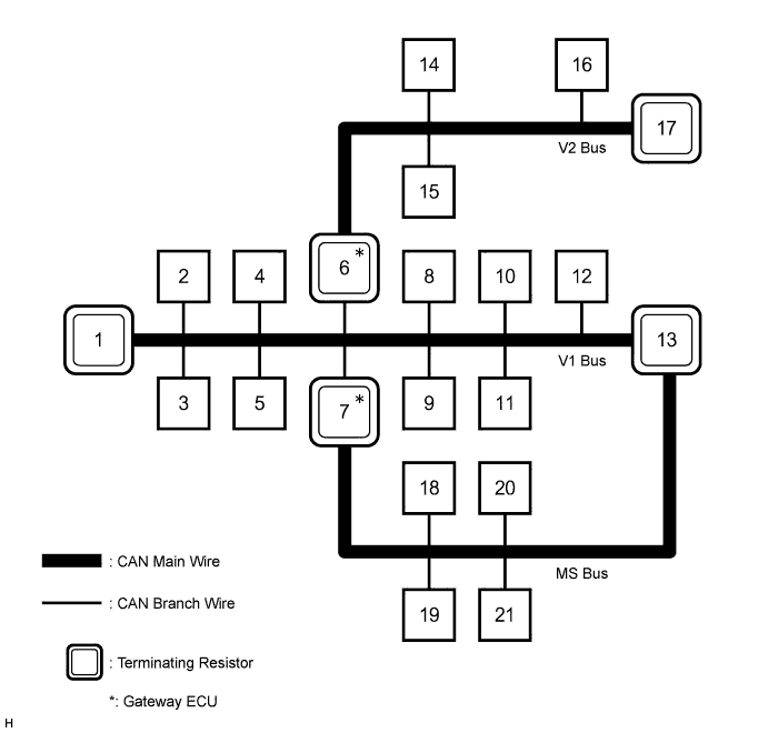
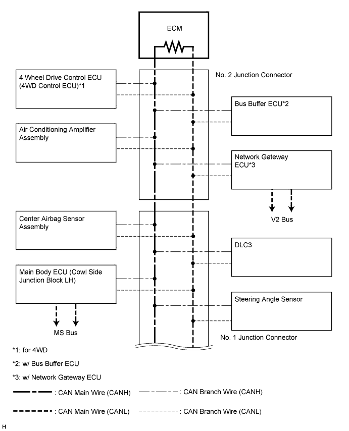
1
| ECM
|
2
| Air conditioning amplifier assembly
|
3
| Bus buffer ECU*1
|
4
| 4 wheel drive control ECU (4WD control ECU)*2
|
5
| Steering angle sensor
|
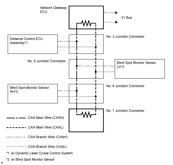
6
| Network gateway ECU*3
|
7
| Main body ECU (cowl side junction block LH)
|
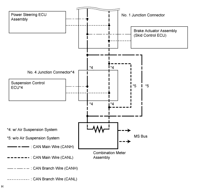
8
| Brake actuator assembly (skid control ECU)
|
9
| Power steering ECU assembly
|
10
| DCL3
|
11
| Center airbag sensor assembly
|
12
| Suspension control ECU*4
|
13
| Combination meter assembly
|
14
| Distance control ECU assembly*5
|
15
| Blind spot monitor sensor LH*6
|
16
| Blind spot monitor sensor RH*6
|
17
| No. 7 junction connector*3
|
18
| Power back door unit assembly (power back door ECU)*7
|
19
| Outer mirror control ECU assembly*8
|
20
| Multiplex tilt and telescopic ECU*8
|
21
| Front power seat switch LH (power seat control ECU)*8
|