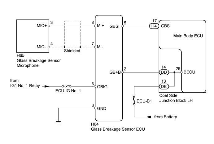
THEFT DETERRENT SYSTEM > Glass Breakage Sensor ECU Circuit |
| 1.READ VALUE USING TECHSTREAM (GLASS BREAKAGE SENSOR) |
Using the Techstream, read the Data List.
| Tester Display | Measurement Item/Range | Normal Condition | Diagnostic Note |
| Glass Break Sensor Detection | Glass breakage sensor detection / ON or OFF | ON: Glass breakage sensor ON OFF: Glass breakage sensor OFF | - |
|
| ||||
| OK | ||
 | ||
| ||
| 2.INSPECT FUSE (ECU-IG No. 1) |
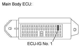 |
Remove the ECU-IG No. 1 fuse from the main body ECU.
Measure the resistance according to the value(s) in the table below.
| Tester Connection | Condition | Specified Condition |
| ECU-IG No. 1 fuse | Always | Below 1 Ω |
|
| ||||
| OK | |
 |
| 3.CHECK HARNESS AND CONNECTOR (GLASS BREAKAGE SENSOR ECU - BATTERY AND BODY GROUND) |
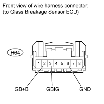 |
Disconnect the H64 glass breakage sensor ECU connector.
Measure the voltage and resistance according to the value(s) in the table below.
| Tester Connection | Switch Condition | Specified Condition |
| H64-2 (GB+B) - H64-6 (GND) | Always | 11 to 14 V |
| H64-3 (GBIG) - H64-6 (GND) | Ignition switch ON | 11 to 14 V |
| Ignition switch off | Below 1 V |
| Tester Connection | Condition | Specified Condition |
| H64-6 (GND) - Body ground | Always | Below 1 Ω |
|
| ||||
| OK | |
|
| 4.CHECK HARNESS AND CONNECTOR (MAIN BODY ECU - GLASS BREAKAGE SENSOR ECU) |
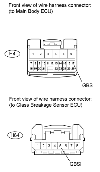 |
Disconnect the H4 main body ECU connector.
Disconnect the H64 glass breakage sensor ECU connector.
Measure the resistance according to the value(s) in the table below.
| Tester Connection | Condition | Specified Condition |
| H4-17 (GBS) - H64-5 (GBSI) | Always | Below 1 Ω |
| H4-17 (GBS) or H64-5 (GBSI) - Body ground | Always | 10 kΩ or higher |
|
| ||||
| OK | |
|
| 5.CHECK HARNESS AND CONNECTOR (GLASS BREAKAGE SENSOR ECU - GLASS BREAKAGE SENSOR MICROPHONE) |
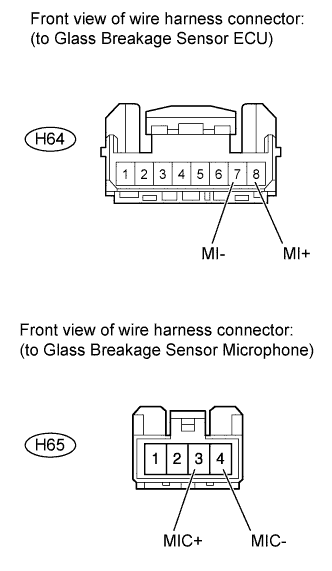 |
Disconnect the H64 glass breakage sensor ECU connector.
Disconnect the H65 glass breakage sensor microphone connector.
Measure the resistance according to the value(s) in the table below.
| Tester Connection | Condition | Specified Condition |
| H64-8 (MI+) - H65-3 (MIC+) | Always | Below 1 Ω |
| H64-7 (MI-) - H65-4 (MIC-) | ||
| H64-8 (MI+) or H65-3 (MIC+)- Body ground | Always | 10 kΩ or higher |
|
| ||||
| OK | |
|
| 6.CHECK GLASS BREAKAGE SENSOR ECU (GLASS BREAKAGE SENSOR OUTPUT) |
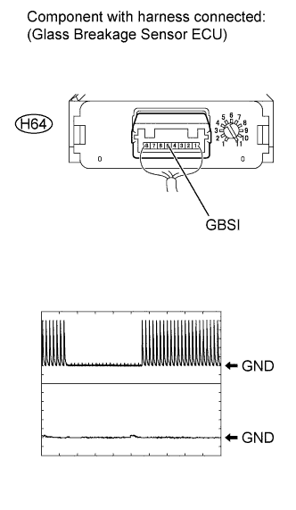 |
Reconnect the H64 glass breakage sensor ECU connector.
Reconnect the H65 glass breakage sensor microphone connector.
Reconnect the H4 main body ECU connector.
Turn the ignition switch to ON.
Using an oscilloscope, check the waveform.
| Test Connector | Tool Setting | Vehicle Condition | Specified Condition |
| H64-5 (GBSI) - Body ground | 1 V/DIV., 50 msec./DIV. | Ignition switch ON. Tap the door glass with a hard object such as your fingernail. | Pulse generation |
|
| ||||
| OK | ||
| ||
| ||

