 |
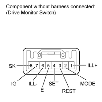
Measure the resistance according to the value(s) in the table below.
- Standard Resistance:
Tester Connection Switch Condition Specified Condition 2 (MODE) - 5 (E) Info switch off 10 kΩ or higher Info switch on Below 1 Ω 3 (REST) - 5 (E) Select reset switch off 10 kΩ or higher Select reset switch on Below 1 Ω 4 (SET) - 5 (E) Setup us/m switch off 10 kΩ or higher Setup us/m switch on Below 1 Ω 7 (IG) - 8 (SK) Sonar switch off 10 kΩ or higher Sonar switch on Below 1 Ω