Home › Engine / Hybrid System ยท 3UR-FE › EMISSION CONTROL › AIR SWITCHING VALVE

AIR SWITCHING VALVE > INSTALLATION

for Preparation Click here


1. INSTALL NO. 3 AIR TUBE


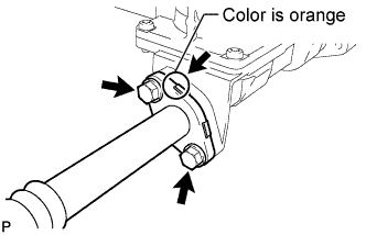
    A158585E02
  1. Install a new gasket and the No. 3 air tube with the 2 bolts.

    Torque:
    10 N*m{ 102 kgf*cm , 7 ft.*lbf }

    NOTICE:
    Make sure that the gasket's claws are not caught between the air tube and electric air control valve assembly.

    HINT:
    The identification color on the flange is orange.
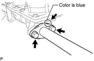


2. INSTALL NO. 2 AIR TUBE


    A158584E02
  1. Install a new gasket and the No. 2 air tube with the 2 bolts.

    Torque:
    10 N*m{ 102 kgf*cm , 7 ft.*lbf }

    NOTICE:
    Make sure that the gasket's claws are not caught between the air tube and electric air control valve assembly.

    HINT:
    The identification color on the flange is blue.


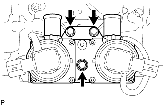
3. INSTALL ELECTRIC AIR CONTROL VALVE ASSEMBLY


    A158586
  1. Install the electric air control valve assembly with the 3 bolts.

    Torque:
    21 N*m{ 214 kgf*cm , 16 ft.*lbf }

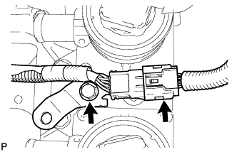
  1. Connect the 2 electric air control valve connectors.


    A158583
  1. Install the bracket with the bolt.

    Torque:
    8.0 N*m{ 82 kgf*cm , 71 in.*lbf }

  1. Connect the knock sensor connector.


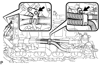
4. INSTALL AIR PIPE SUB-ASSEMBLY
  1. Connect the 2 No. 1 air hoses to the air pipe.


    A158582
  1. Connect the air pipe to the electric air control valve assembly, and install the air pipe with the 2 bolts.

    Torque:
    10 N*m{ 102 kgf*cm , 7 ft.*lbf }


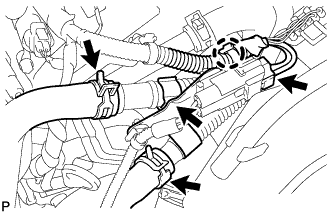
    A158575
  1. Connect the air pump connector clamp holder.

  1. Attach the wire harness claw.

  1. Connect the electric air control valve connector.

  1. Connect the No. 2 air injection system hose and No. 3 air injection system hose.


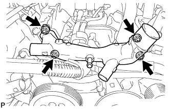
5. INSTALL FRONT WATER BY-PASS JOINT


    A158579
  1. Install 2 new gaskets and the front water by-pass joint with the 4 nuts.

    Torque:
    21 N*m{ 214 kgf*cm , 16 ft.*lbf }

  1. Connect the engine coolant temperature sensor connector.


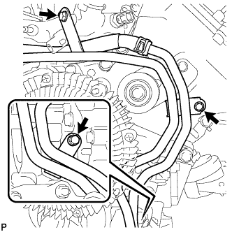
6. CONNECT WATER BY-PASS PIPE HOSE (w/ Trailer Towing System)


    A158578
  1. Connect the water by-pass pipe hose with the 3 bolts.

    Torque:
    10 N*m{ 102 kgf*cm , 7 ft.*lbf }


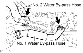
7. CONNECT NO. 2 WATER BY-PASS HOSE


    A158577E01
  1. Connect the No. 2 water by-pass hose to the water by-pass joint.


8. CONNECT NO. 1 WATER BY-PASS HOSE
  1. Connect the No. 1 water by-pass hose to the water by-pass joint and water inlet housing.


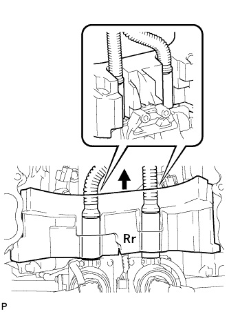
9. INSTALL NO. 1 ENGINE COVER


A158656

NOTICE:
Make sure that the No. 1 engine cover is level with the top surface of the intake port of the cylinder head for 1 and 2.

  1. Install the No. 1 engine cover.

    HINT:
    1. Align the No. 1 engine cover cutouts with the air tube.
    2. Align the No. 1 engine cover with the air switching valve surface and cylinder head wall.


10. CONNECT FUEL TUBE CLAMP


    A158580
  1. Connect the fuel tube clamp to the bracket.


11. INSTALL NO. 2 CYLINDER HEAD COVER


A158538

NOTICE:
Make sure that the No. 2 cylinder head cover is level with the top surface of the intake port of the cylinder head.

  1. Install the No. 2 cylinder head cover.

    HINT:
    1. Align the No. 2 cylinder head cover cutout with the air tube.
    2. Align the No. 2 cylinder head cover with the front water by-pass joint and cylinder head wall.


12. INSTALL FAN SHROUD


    A151842
  1. Install the fan pulley to the fan bracket.

  1. Place the shroud together with the coupling fan between the radiator and engine.

    NOTICE:
    Be careful not to damage the radiator core.

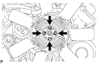
  1. Temporarily install the fluid coupling fan to the fan bracket with the 4 nuts. Tighten the nuts as much as possible by hand.


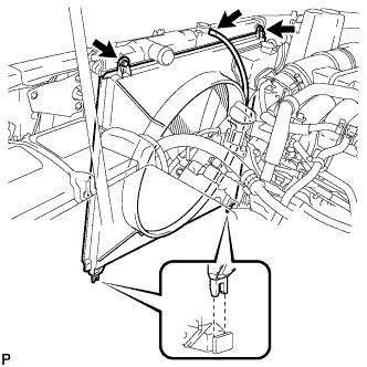
    A183238
  1. Attach the shroud claws to the radiator as shown in the illustration.

  1. Install the shroud with the 2 bolts.

    Torque:
    6.5 N*m{ 66 kgf*cm , 58 in.*lbf }

  1. Connect the reservoir hose to the upper radiator tank.


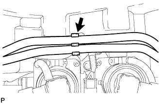
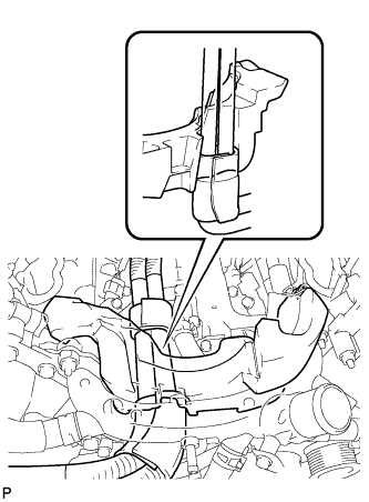
    A187694
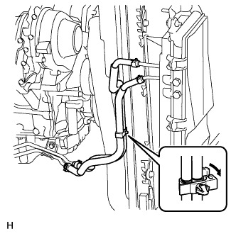
  1. for Condenser with Separate Oil Cooler:
    Pass the 2 hoses through the flexible hose clamp and close the clamp as shown in the illustration.

    HINT:
    Align the hose clamp with the white paint mark on the hose, and install the hose clamp so that the hose clamp lock is between the fan shroud stoppers.

  1. Install the fan and generator V belt .

  1. Tighten the 4 nuts of the fluid coupling fan.

    Torque:
    21 N*m{ 214 kgf*cm , 16 ft.*lbf }


13. INSTALL OUTLET RADIATOR HOSE


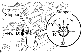
    A183234E01
  1. Connect the outlet radiator hose to the water inlet housing.


14. INSTALL INLET RADIATOR HOSE


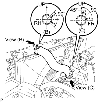
    A198570E01
  1. Install the inlet radiator hose.

    HINT:
    Install the hose so that the direction of the hose clamp is as indicated in the illustration.


15. INSTALL INTAKE MANIFOLD
  1. Install the intake manifold (Click here).


16. INSTALL EXHAUST MANIFOLD SUB-ASSEMBLY
  1. Install the exhaust manifold (Click here).