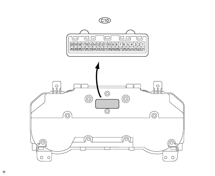
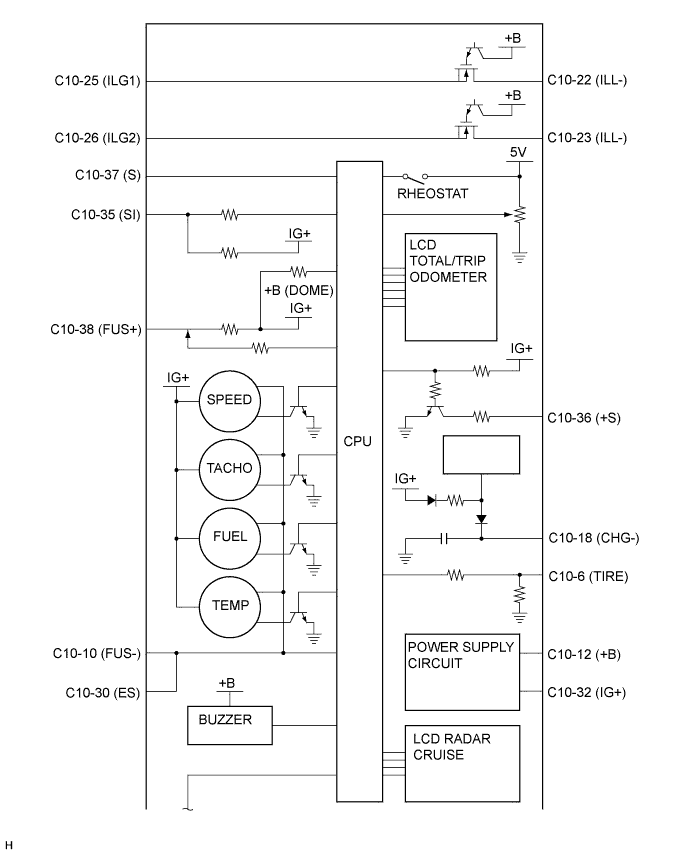
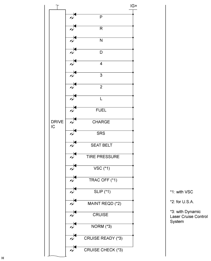
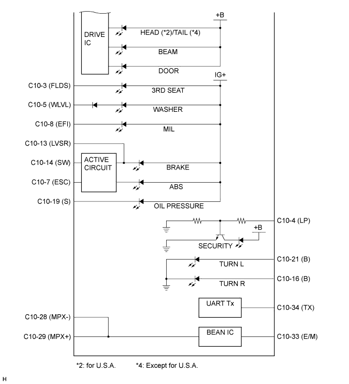
Terminals No. (Symbols)
| Wiring Color
| Terminal Description
| Condition
| Specified Condition
|
C10-3 (FLDS) (*1) - Body ground
| R-W - Body ground
| 3RD SEAT indicator light signal
(Folding seat indicator light signal)
| Turn the ignition switch to the ON position, 3RD SEAT indicator light ON
| Below 3 V
|
Turn the ignition switch to the ON position, 3RD SEAT indicator light OFF
| 10 to 14 V
|
C10-4 (LP) (*2) - Body ground
| B - Body ground
| SECURITY indicator light signal
| SECURITY indicator light ON
| 8 to 14 V
|
SECURITY indicator light OFF
| Below 1 V
|
C10-5 (WLVL) - Body ground
| L-R - Body ground
| WASHER indicator light signal
| Turn the ignition switch to the ON position, WASHER indicator light OFF
| 10 to 14 V
|
Turn the ignition switch to the ON position, WASHER indicator light ON
| Below 1 V
|
C10-6 (TIRE) - Body ground
| GR-L - Body ground
| TIRE PRESSURE warning light signal
| Turn the ignition switch to the ON position, TIRE PRESSURE warning light ON
| 0.9 to 3.2 V
|
Turn the ignition switch to the ON position, TIRE PRESSURE warning light OFF
| 3.2 V or higher
|
C10-7 (ESC) - Body ground
| R-W - Body ground
| ABS warning light signal
| Turn the ignition switch to the ON position, ABS warning light ON
| 10 to 14 V
|
Turn the ignition switch to the ON position, ABS warning light OFF
| Below 1 V
|
C10-8 (EFI) - Body ground
| B-Y - Body ground
| Malfunction Indicator Lamp signal
(Check engine warning light signal)
| Turn the ignition switch to the ON position, MIL ON
| Below 1 V
|
Turn the ignition switch to the ON position, MIL OFF
| 10 to 14 V
|
C10-10 (FUS-) - Body ground
| BR-B - Body ground
| Ground (Fuel ground)
| Always
| Below 1 V
|
C10-12 (+B) - Body ground
| W-L - Body ground
| Battery
| Always
| 10 to 14 V
|
C10-13 (LVSR) - Body ground
| Y-R - Body ground
| Brake fluid level warning switch signal
| Turn the ignition switch to the ON position, BRAKE warning light OFF
| 10 to 14 V
|
Turn the ignition switch to the ON position, BRAKE warning light ON
| Below 1 V
|
C10-14 (SW) - Body ground
| Y-B - Body ground
| BRAKE warning light signal
| Turn the ignition switch to the ON position, BRAKE warning light ON
| 10 to 14 V
|
Turn the ignition switch to the ON position, BRAKE warning light OFF
| Below 1 V
|
C10-16 (B) - Body ground
| G-Y - Body ground
| TURN R indicator light signal
| Turn the ignition switch to the ON position, TURN R indicator light OFF
| Below 1 V
|
Turn the ignition switch to the ON position, TURN R indicator light ON
| 10 to 14 V
|
C10-18 (CHG-) - Body ground
| W-G - Body ground
| CHARGE warning light signal
| Turn the ignition switch to the ON position, CHARGE warning light OFF
| Below 1 V
|
Turn the ignition switch to the ON position, CHARGE warning light ON
| 10 to 14 V
|
C10-19 (S) - Body ground
| Y-B - Body ground
| OIL PRESSURE warning light signal
| Turn the ignition switch to the ON position, OIL PRESSURE warning light OFF
| Below 1 V
|
Turn the ignition switch to the ON position, OIL PRESSURE warning light ON
| 10 to 14 V
|
C10-21 (B) - Body ground
| G-B - Body ground
| TURN L indicator light signal
| Turn the ignition switch to the ON position, TURN L indicator light OFF
| Below 1 V
|
Turn the ignition switch to the ON position, TURN L indicator light ON
| 10 to 14 V
|
C10-22 (ILL-) - Body ground
| W-G - Body ground
| Illumination signal
| Turn the ignition switch to the ON position, light control switch OFF
| Below 1 V
|
Turn the ignition switch to the ON position, light control switch ON
| 10 to 14 V
|
C10-23 (ILL-) - Body ground
| W-R - Body ground
| Illumination signal
| Turn the ignition switch to the ON position, light control switch OFF
| Below 1 V
|
Turn the ignition switch to the ON position, light control switch ON
| 10 to 14 V
|
C10-25 (ILG1) - Body ground
| W-B - Body ground
| Ground
(Illumination ground)
| Always
| Below 1 V
|
C10-26 (ILG2) - Body ground
| W-B - Body ground
| Ground
(Illumination ground)
| Always
| Below 1 V
|
C10-28 (MPX-) - Body ground
| V - Body ground
| Multiplex Communication Line
| Always
| 10 to 14 V
|
C10-29 (MPX+) - Body ground
| R-L - Body ground
| Multiplex Communication Line
| Always
| 10 to 14 V
|
C10-30 (ES) - Body ground
| BR - Body ground
| Ground
(Signal ground)
| Always
| Below 1 V
|
C10-32 (IG+) - Body ground
| B-R - Body ground
| Ignition switch signal
| Turn the ignition switch off
| Below 1 V
|
Turn the ignition switch to the ON position
| 10 to 14 V
|
C10-33 (E/M) - Body ground
| W - Body ground
| Accessory meter signal
| Communication Line
| -
|
C10-34 (TX) - Body ground
| R - Body ground
| Accessory meter signal
| Communication Line
| -
|
C10-35 (SI) - Body ground
| GR - Body ground
| Speed signal (Input)
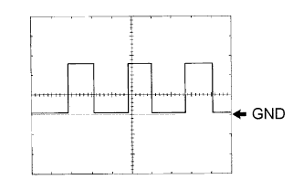
| Turn the wheel slowly
| Pulse generation
(See waveform 1)
|
C10-36 (+S) - Body ground
| V-W - Body ground
| Speed signal (Output)
| Turn the ignition switch off
| Below 1 V
|
Turn the ignition switch to the ON position
| 10 to 14 V
|
C10-37 (S) - Body ground
| B-O - Body ground
| Tachometer signal
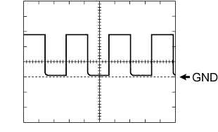
| Engine idle speed
| Pulse generation
(See waveform 2)
|
C10-38 (FUS+) - Body ground
| Y-G - Body ground
| Fuel signal
| Turn the ignition switch to the ON position, fuel level is FULL
| Below 2 V
|
Turn the ignition switch to the ON position, fuel level is EMPTY
| 5 to 8 V
|