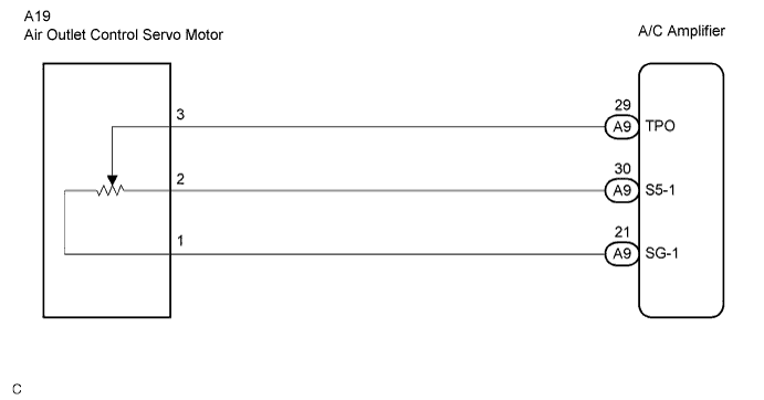
DTC B1433/33 Air Outlet Damper Position Sensor Circuit |
| DTC No. | DTC Detection Condition | Trouble Area |
| B1433/33 | Open or short in power source circuit in air outlet damper position sensor circuit. |
|
| 1.READ VALUE USING TECHSTREAM |
Connect Techstream to the DLC3.
Turn the ignition switch to the ON position and turn Techstream on.
Select the items below in the Data List, and read the displays on Techstream.
| Tester Display | Measurement Item/Range | Normal Condition | Diagnostic Note |
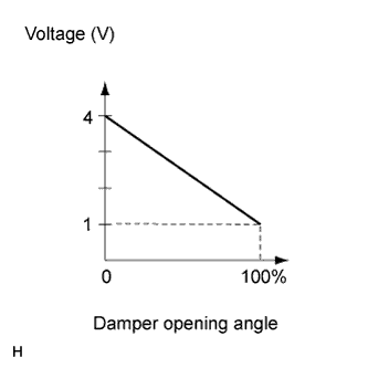
| Air Outlet Damper Position | Air outlet damper position / min.: -14%, max.: 113.5% | Damper is at "FACE": 0% Damper is at "FACE/FOOT": 33.5% Damper is at "FOOT": 53.5% Damper is at "FACE/DEF": 73.5% Damper is at "DEF": 100% | Open in the circuit: 50.0% |
| Air Outlet Damper Target | Air outlet damper target position / min.: -14%, max.: 113.5% |
| Result | Proceed to |
| NG | A |
| OK (When troubleshooting according to the PROBLEM SYMPTOM TABLE) | B |
| OK (When troubleshooting according to the DTC) | C |
|
| ||||
|
| ||||
| A | |
 |
| 2.INSPECT AIR OUTLET CONTROL SERVO MOTOR |
 |
Remove the air outlet control servo motor.
Disconnect the connector from the air outlet control servo motor.
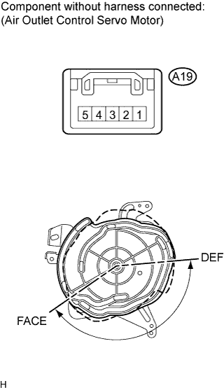
Measure the resistance according to the value(s) in the table below.
| Tester Connection | Condition | Specified Condition |
| A19-2 - A19-1 | Always | 4.2 to 7.8 kΩ |
Measure the resistance according to the value(s) in the table below.
| Tester Connection | Condition | Specified Condition |
| A19-3 - A19-1 | DEF position | 0.8 to 1.6 kΩ |
| A19-3 - A19-1 | FACE position | 3.4 to 6.2 kΩ |
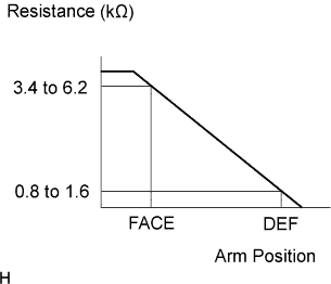 |
As the air outlet control servo motor moves from the FACE side to the DEF side, the resistance decreases gradually without interruption.
|
| ||||
| OK | |
|
| 3.CHECK HARNESS AND CONNECTOR (AIR OUTLET CONTROL SERVO MOTOR - A/C AMPLIFIER) |
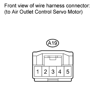 |
Disconnect the connector from the A/C amplifier.
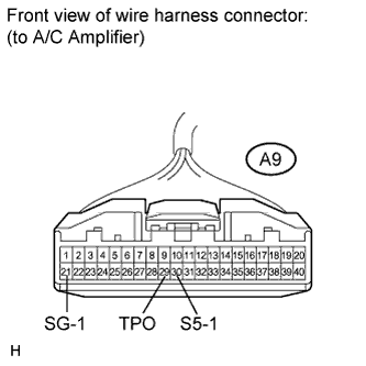 |
Measure the resistance according to the value(s) in the table below.
| Tester Connection | Condition | Specified Condition |
| A9-29 (TPO) - A19-3 | Always | Below 1 Ω |
| A9-21 (SG-1) - A19-1 | Always | Below 1 Ω |
| A9-30 (S5-1) - A19-2 | Always | Below 1 Ω |
| A9-29 (TPO) - Body ground | Always | 10 kΩ or higher |
| A9-21 (SG-1) - Body ground | Always | 10 kΩ or higher |
| A9-30 (S5-1) - Body ground | Always | 10 kΩ or higher |
|
| ||||
| OK | ||
 | ||
| ||
